


DM4170 – Installation Manual
Installing the DM4170
204.4308.03
21
specifications of the country where it is installed.
Step 3
•
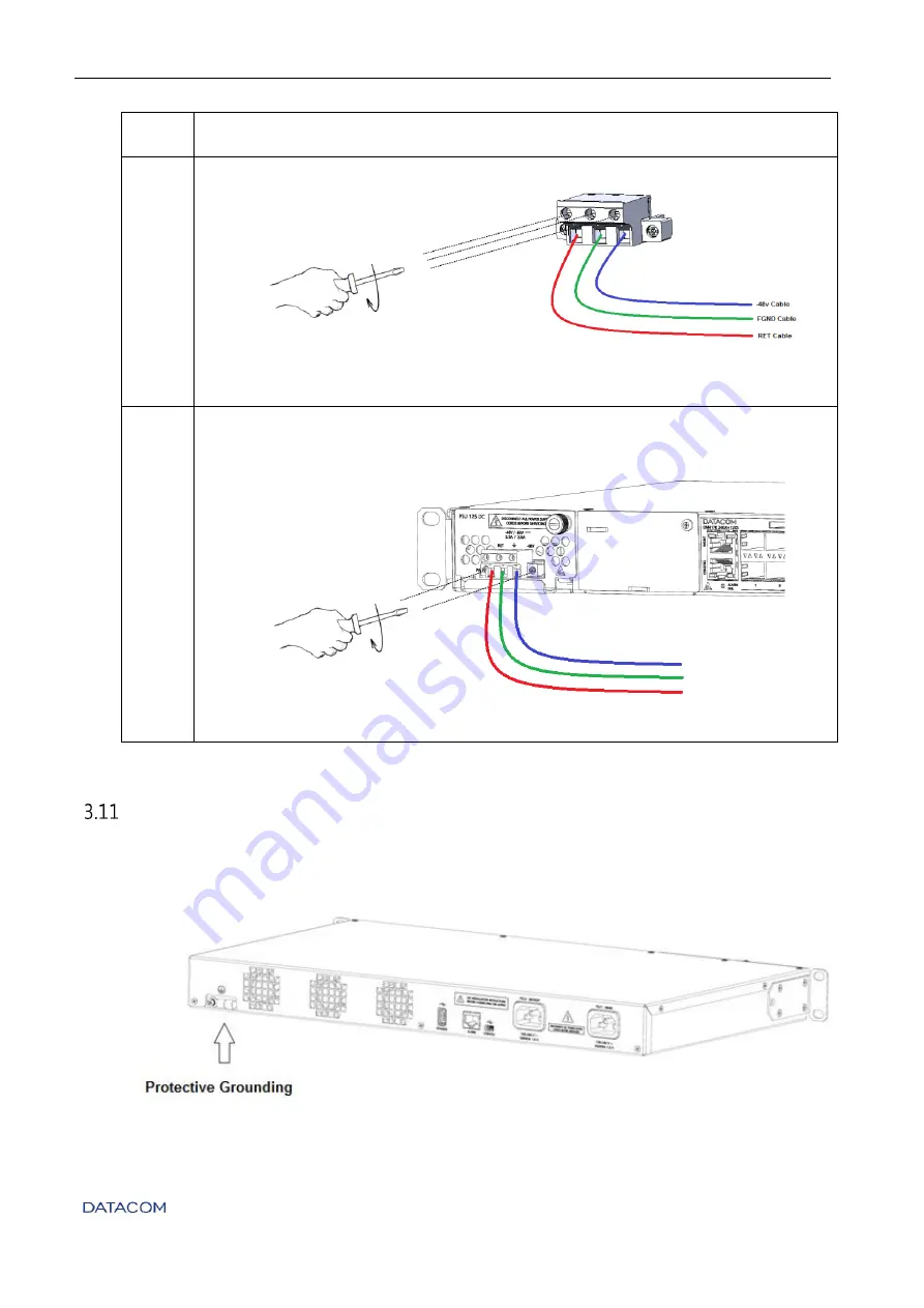
Using a 1/8" screwdriver (number 0), screw the cable as shown below:
Figure 16 – Installing the cable to the TERMINAL BLOCK
Step 4
•
Before the cable is powered, screw the connector with the cable installed on
the PSU 125 DC, using the same 1/8" screwdriver (number 0) used above, as
shown below:
Figure 17 – Installing the cable mounted to the TERMINAL BLOCK on the PSU 125 DC
Table 13 – Installing the PSU 125 DC power supply
P
ROTECTIVE
G
ROUNDING
The DM4170 switches have a Protective Ground point on the rear panel. This connector must
be connected to the installation ground (FGND) as instructed in the
chapter.
Figure 18 – Protective Grounding in DM4170