background image

4 Using the control module 


Clarity Controls


12 

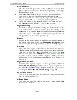
Changes the detector range (as set before the analysis on the 

DET X

 tab) during the course of the analysis. Range 

x1


corresponds to value 

0

, range 

x10

-1

 to value 

1

x10

-2

 to value 

2

x10

-3

 to value 

3

 and 

x10

-4

 to value 

4

Det 1(..4) Current 

Changes the current value of the detector (if the current for 
the given detector has any sense). The new value should be 
in range and units dependent on the type of the detector - 

FTD

 detector has the range of values 

0.00-10.00 pA

ECD


detector 

0.00-2.00 nA

 and 

TCD

 detector 

0-200 mA

All 4 possible detectors are listed, even if they are not present 
and configured in the 

Shimadzu GC-2014C Setup

 dialog. Those 

not configured will have the text in the format 

Det #X Polarity


etc. with the # character - these shouldn't be used in the 

Time 

Events table

Event Operation 

Performs an event operation defined by the event code. 
These codes may be used as a positive number or negative 
number, in which case the opposite of the operation is 
performed. For example, event code 

51

 performs the 

autozero operation on detector 1, while 

-51

 event code 

cancels the zero adjustment on detector 1. The basic event 
codes and their functions are: 

Event Code 

Function 

51 

Autozeroes the Detector 1 

52 

Autozeroes the Detector 2 

53 

Autozeroes the Detector 3 

54 

Autozeroes the Detector 4 

Tab 1: Event codes 

For more event codes please see Shimadzu hardware 
documentation. 

Temperature of INJ1(2), DET1(2), AUX3(..5) 

Changes the temperature of the particular temperature 
zone. The initial temperature is set on the 

Oven/Zones

 tab, 

but can be changed later during the analysis this way. The 

Value

 column should hold the temperature in °C. 

Program stop 

Stops the GC control program. The value entered into the 

Value

 column should be set to 

XY

, where 

X

 is the number of 

Summary of Contents for Shimadzu GC2014C APC/AFC

Page 1: ...trols Shimadzu GC 2014C GC ENG Code Rev M113 26C Date 13 5 2008 Phone 420 251 013 400 DataApex Ltd 2008 Fax 420 251 013 401 Podohradska 1 clarity dataapex com 155 00 Prague 5 www dataapex com The Czec...

Page 2: ...emarks of DataApex Ltd Microsoft and WindowsTM are trademarks of Microsoft Corporation DataApex reserves the right to make changes to manuals without prior notice Updated manuals can be downloaded fro...

Page 3: ...14C setup communication 3 3 3 Clarity Configuration 4 4 Using the control module 6 4 1 Hardware Configuration 6 4 2 Method Setup GC 7 4 2 1 Oven Zones 7 4 2 2 INJ 1 2 8 4 2 3 DET 1 4 9 4 2 4 Time Even...

Page 4: ...VE orange capital italics marks the state of the station or its part Administrator green italics refers to a value or text inserted into a field The bold text is sometimes also used for important part...

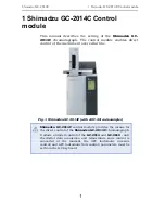
Page 5: ...erial line Fig 1 Shimadzu GC 2014C with AOC 20i autosampler Shimadzu GC 2014C control module provides the means for the direct control of the Shimadzu GC 2014C chromatograph It allows a limited contro...

Page 6: ...n the PC Modern computers usually have only 1 if any serial COM port installed To use more devices requiring the port the MultiCOM adapter p n MC01 is available Serial cross DB9F DB9F cable p n SK01 C...

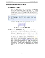
Page 7: ...iring is described in the picture Fig 2 Serial cross cable DB9F DB9F 3 2 Shimadzu GC 2014C setup communication The GC must be fully configured prior to connecting to Clarity No special settings have t...

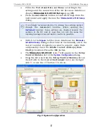
Page 8: ...onfiguration In the System Configuration dialog press the Add button to invoke the Available Control Modules dialog Fig 3 Available Control Modules Select the Shimadzu GC 2014C in the GC section and p...

Page 9: ...ed against the settings of the GC and in case they are not the same the warning message is issued and no control is possible Switch to the Signals tab for more details see the Shimadzu GC 2014C Setup...

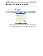
Page 10: ...etting of the GC control method 4 1 Hardware Configuration Menu Path Instrument Method GC Control GC Status Fig 6 Hardware Configuration This dialog is invoked by pressing the GC Status button in the...

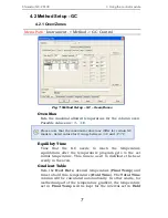
Page 11: ...it range between 400 and 470 C Equilibry Time Time that the GC needs to reach the temperature equilibrium after the temperature program gets to the set initial temperature This time is used to distrib...

Page 12: ...ead from GC it serves for the information purposes only 4 2 2 INJ 1 2 Menu Path Instrument Method GC Control Fig 8 Method Setup GC INJ 1 This tab governs the settings concerning the injection port of...

Page 13: ...rameters for a detector configured in the Shimadzu GC 2014C Setup dialog Particular fields may vary according to the type of the detector set On Off Switches the detector on and off The detector switc...

Page 14: ...larity or vice versa polarity Range Applies on the analog detector signal before its processing to the digital data directly in the Shimadzu GC 2014C This value serves for the compensation of the over...

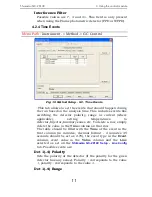
Page 15: ...ere applicable setting temperatures to detector injector auxiliary zones etc To delete a row simply delete the value in the Time column on that row The table should be filled with the Time of the even...

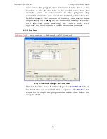
Page 16: ...n the Time Events table Event Operation Performs an event operation defined by the event code These codes may be used as a positive number or negative number in which case the opposite of the operatio...

Page 17: ...e number of method runs doesn t have any meaning for Clarity as the method is usually sent after each injection thus resetting the counter after each injection For more details consult Shimadzu manual...

Page 18: ...tograph will do nothing when the analysis is completed Set Off after analysis The chromatograph performs the System Off function check Shimadzu GC 2014C manual for more details This function is useful...

Page 19: ...the leakage of possibly dangerous gasses hydrogen into the laboratory environment Zero at ready When checked the chromatograph performs the autozero action after it becomes READY Auto flame ON When c...

Page 20: ...control module Clarity Controls 16 4 2 7 Gradients Menu Path Instrument Method GC Control Fig 13 Method Setup GC Gradients This tab displays the temperature gradient as set on the Method Setup GC Ove...

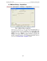
Page 21: ...to set the particular Sampling Rate on the appropriate tab This sampling rate in fact states the frequency of the data sending from the Shimadzu GC 2014C detector to Clarity it has nothing to do with...

Page 22: ...n oven Besides that it also shows the run time of the analysis System On Allows to switch the chromatograph on It starts the temperature program in the column oven detectors and injectors System Off S...

Page 23: ...Autodetect function because these settings are checked against those in the GC when opening the Instrument window If they don t match the control is not possible The only parts of the dialog that can...

Page 24: ...log Piping tab Fig 17 Shimadzu GC 2014C Setup Piping Car 1 3 Allows to set the possible operation modes for carrier gasses For Shimadzu GC 2014C chromatographs without automatic flow control function...

Page 25: ...ount Defines the number of signals that will be transferred to the Clarity These signals correspond to Clarity detectors and will have their own sub tabs in the Method Setup Acquisition dialog if conf...
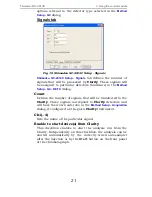
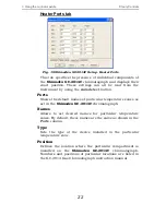
Page 26: ...the default names of particular temperature zones as set in the Shimadzu GC 2014C chromatograph Names Allows to set desired names for particular temperature zones By default these names are the same...

Page 27: ...Shimadzu GC 2014C Setup Line Config This tab shows the position of particular components on the analytical lines in the chromatograph Up to four independent lines may be configured All settings on thi...

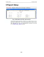
Page 28: ...from all major windows Fig 21 Shimadzu GC 2014C report preview All chromatograph specific settings e g temperatures set to particular temperature zones are reported as a part of the data displayed by...

Reviews: