


Chapter 4
48
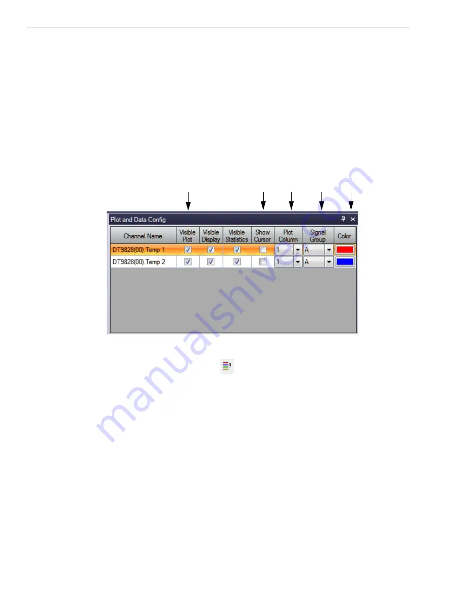
Configure the Appearance of the Channel Plot Window
Configure the appearance of the Channel Plot window as follows:
1.
In the
Plot and Data Config
window, set up the following parameters:
a.
Ensure that the
Visible Plot
column is checked for both enabled channels.
b.
Leave the
Show Cursor
column unchecked for all three enabled channels.
c.
Under
Plot Column
, use the default plot column setting of 1 for both enabled
channels.
d.
Under the
Signal Group
column, select
A
for both thermocouple channels.
e.
Under the
Color
column, assign a unique color to each trace.
2.
In the display area, click the tab for the
Channel Plot
window.
3.
Click the
Show Legend
control (
) on the toolbar.
4.
Change the text for the label on the x-axis, by doing the following:
a.
Right-click on the label.
b.
Select
Edit Label
.
c.
Enter the following text:
Thermocouple Channels.
The Channel Plot window should appear as follows:
Summary of Contents for DT9828
Page 1: ...DT9828 User s Manual UM 24984 A Title Page ...
Page 4: ......
Page 8: ...Contents 8 ...
Page 12: ...About this Manual 12 ...
Page 13: ...13 1 Overview Features 14 Supported Software 16 Accessories 18 Getting Started Procedure 19 ...
Page 20: ...Chapter 1 20 ...
Page 21: ...Part 1 Getting Started ...
Page 22: ......
Page 30: ...Chapter 2 30 ...
Page 49: ...Verifying the Operation of a Module 49 ...
Page 54: ...Chapter 4 54 ...
Page 55: ...Part 2 Using Your Module ...
Page 56: ......
Page 57: ...57 5 Principles of Operation Analog Input Features 59 Digital I O Features 67 ...
Page 80: ...Chapter 6 80 ...
Page 86: ...Chapter 7 86 ...
Page 92: ...Chapter 8 92 ...
Page 106: ...Appendix A 106 ...
Page 112: ...Appendix B 112 ...


