Wiring Signals
97
5
5
5
5
5
5
5
5
5
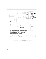
Figure 49: Cascading Counters for the DT740
(Shown for One-Shot Using Counters 0 and 1 and External Gate 1)
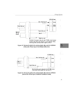
, and
show examples of connecting
pulse output applications to the STP268 screw terminal panel. Other
combinations of signals can be used.
DT740 Panel
TB58
Signal Source
Digital Ground
User Clock Input 0
TB61
TB64
Digital Ground
Gate 1
One-Shot
Trigger
TB59
TB62
User
Counter
Output 0
User Clock
Input 1
TB57
TB108
Digital Shield
Summary of Contents for DT3010 Series
Page 1: ...R DT3010 Series UM 16868 C Getting Started Manual ...
Page 22: ...Chapter 2 12 ...
Page 36: ...Chapter 3 26 ...
Page 114: ...Chapter 5 104 ...
Page 136: ...Appendix A 126 ...
Page 142: ...Index 132 ...


