Adding or replacing a graphics controller (550 series)
7-22
014–002250–01
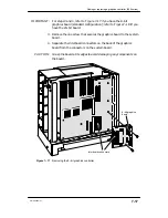
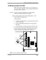
6. Align the graphics board bracket screw holes with the holes in the
computer unit rear panel bulkhead; then, insert and secure the
screws as shown in Figure 7–22. For an 8–bit graphics controller,
there are two screws; for a 24–bit controller, there are three screws.
Computer unit
rear panel
Secure two
or three
screws.
(24–bit
controller
only)
Figure 7–22 Securing the I/O expansion board to the computer unit bulkhead
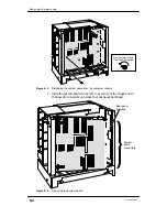
7. Reinstall the cover as described in Chapter 4, “Expanding and
maintaining your computer system.”
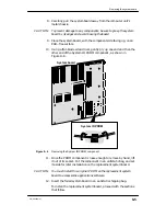
To connect monitor and mouse cables to a graphics controller, refer
to Chapter 2, “Setting up the computer unit.”
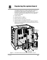
To test a new or replacement board, you should run a diagnostics
acceptance test after your next powerup. Refer to the manual Using
AViiON
Diagnostics and the AV/Alert
sm
Support System for
instructions on running a hardware acceptance test or other
diagnostic utilities.
End of Chapter
Summary of Contents for AViiON 550 Series
Page 2: ......
Page 6: ......
Page 12: ...Joining our users group x 014 002250 01 ...
Page 86: ...Opening and closing the computer unit 4 12 014 002250 01 ...
Page 96: ...Installing a drive assembly 5 10 014 002250 01 ...
Page 188: ......
Page 191: ......

