Configuring VME Option Boards
2-49
014–001867
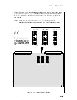
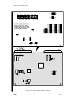
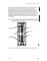
qd
VFC
DAUGHTER
CARD
COMPANION
BOARD
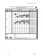
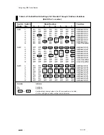
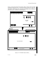
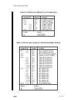
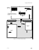
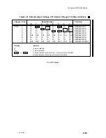
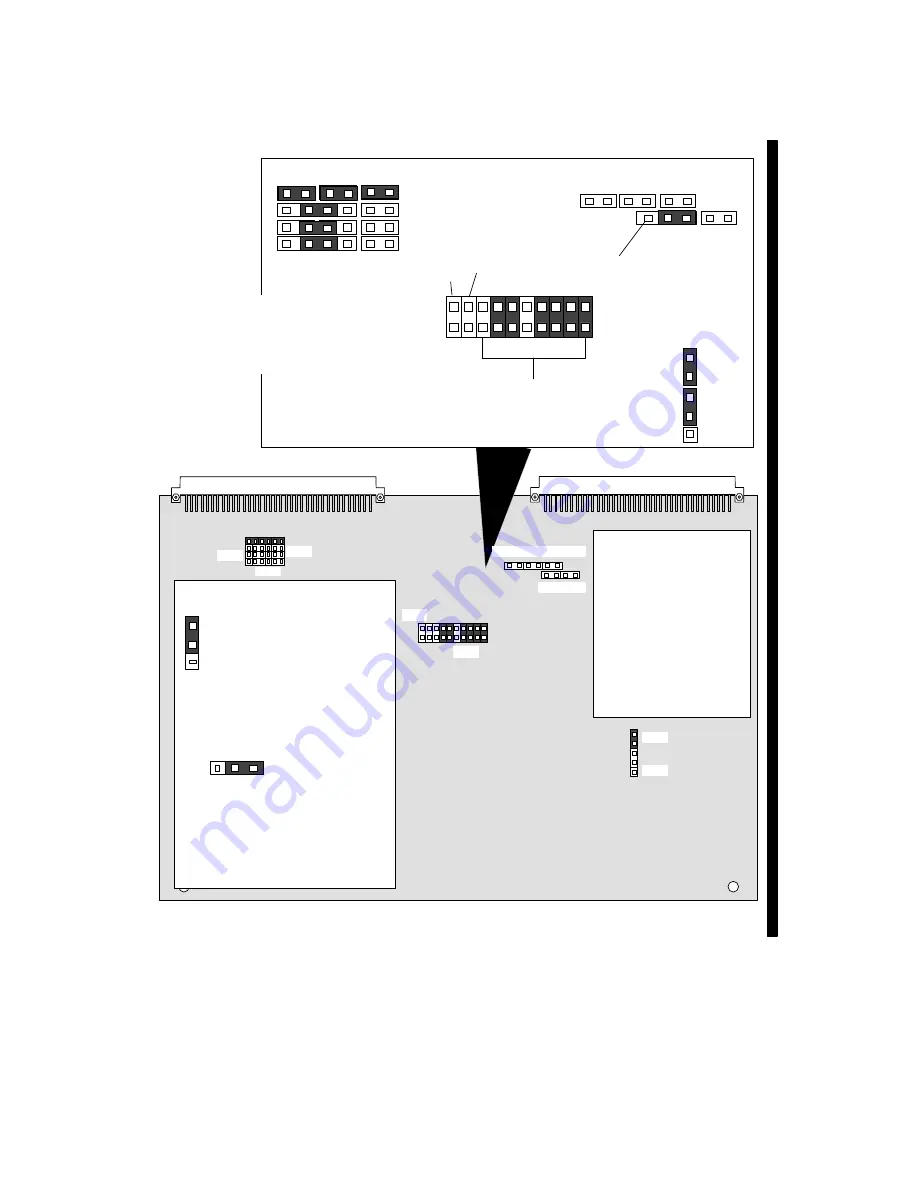
The jumper configuration shown here is
for board position 0. To configure for
other board positions, refer to the tables
that follow.
1
4
JA9
JA10
JA8
JA4
JA5
JA6
J14 pin1
J15
J14
JA11
JA7
JA3
1
8
JA1
J13
1
JA1
JA11
JA3
JA1
J13
JA7
J14
J15
JA6
JA5
JA4
JA9
JA10
JA8
JA2
1
1
Figure 2–19 VFC Board Jumper Locations
Summary of Contents for AViiON 5000 Series
Page 2: ......
Page 6: ......
Page 12: ...Preface x 014 001867 ...
Page 86: ...Configuring VME Option Boards 2 52 014 001867 ...
Page 144: ...Connecting External Devices to VME Option Boards 4 44 014 001867 ...
Page 150: ...VME Backplane Connector Signals and Power Distribution A 6 014 001867 ...
Page 196: ...Assigning VME Data Bus and Interrupt Priorities E 10 014 001867 ...
Page 206: ......
Page 210: ...Appendix Title ...

