Configuring VME Option Boards
2-3
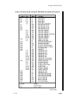
014–001867
To install or remove jumpers from a printed-circuit board, follow these steps after
setting up an ESD kit:
1. Remove the controller board from its antistatic bag and place it, component-side
up, on a static-free surface. Do not touch the electronic components on the
board; handle printed-circuit boards by the edges only.
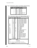
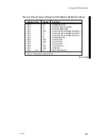
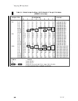
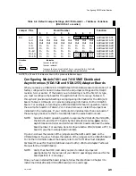
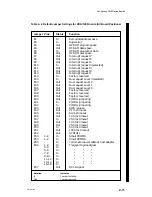
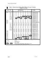
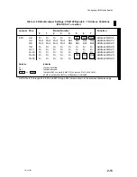
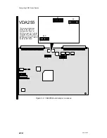
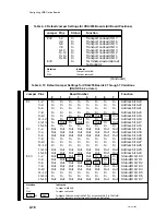
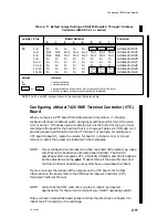
2. Refer to the device specific section later in this chapter for a listing of the
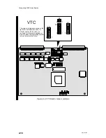
jumper(s) you need to change. The jumper board locations are given in the
associated illustrations. If you require further information on the jumper
functions, refer to the manual that came with your device.
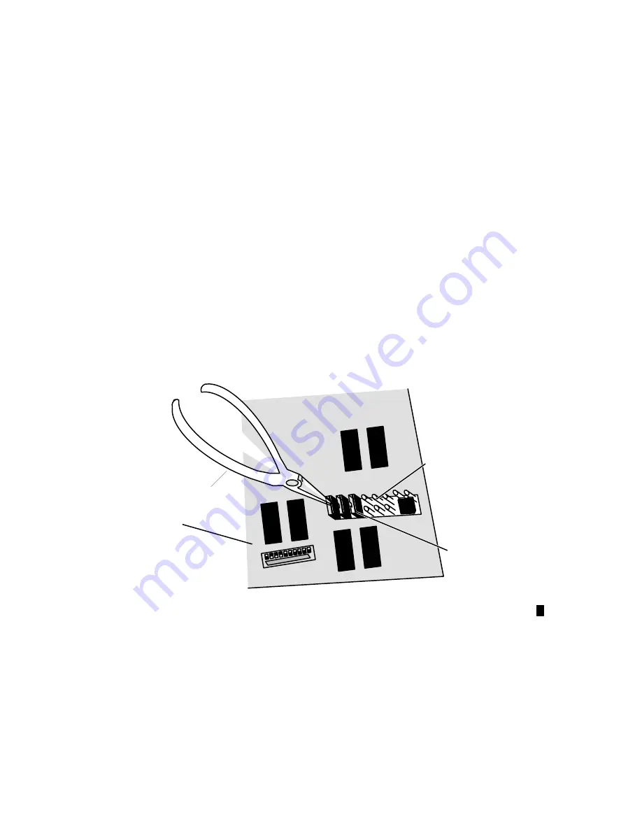
3. Use needlenose pliers to carefully pull the proper jumper(s) straight up and off
the pin. Do not pull the plug from side to side, twist it, or otherwise risk
bending or breaking the pins.
Use needlenose pliers to carefully align and start pushing jumpers straight onto
the proper pins; then push the jumper completely onto the pins with your
finger, if necessary. You should not need to force a jumper onto the board if you
install the proper jumper in the right location.
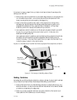
Figure 2–1 illustrates how to install and remove jumpers from a typical row of pins.
Jumper pins
Jumper plugs
Printed-circuit board
Nonmagnetic
needlenose pliers
Figure 2–1 Removing or Installing Jumper Plugs
Setting Switches
Some boards use DIP switches to determine certain settings. To alter switch settings
on a printed-circuit board, follow these steps after setting up an ESD kit:
1. Remove the device from its antistatic bag and place it, component-side up, on a
static-free surface. Do not touch the electrical components on the board; handle
printed-circuit boards by the edges only.
2. Refer to your device-specific technical manual to determine the location and
in/out position of the switches you need to change.
Summary of Contents for AViiON 5000 Series
Page 2: ......
Page 6: ......
Page 12: ...Preface x 014 001867 ...
Page 86: ...Configuring VME Option Boards 2 52 014 001867 ...
Page 144: ...Connecting External Devices to VME Option Boards 4 44 014 001867 ...
Page 150: ...VME Backplane Connector Signals and Power Distribution A 6 014 001867 ...
Page 196: ...Assigning VME Data Bus and Interrupt Priorities E 10 014 001867 ...
Page 206: ......
Page 210: ...Appendix Title ...

