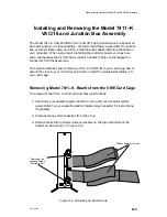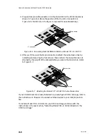
Special Instructions for Model-Specific VME Hardware
D-5
014–001867
Attaching the Model 7411–K Junction Box to the VAC/16
To connect a Model 7411–K VAC/16 controller to its J-box assembly(ies), use the
instructions that follow.
NOTE:
The illustrations in this section show a Model 7411–K VAC/16 that has not
yet been installed in an AViiON computer chassis. (For ease of assembly,
we recommend that you attach the J-box assembl(ies) before installing a
new or replacement Model 7411–K in your VME card cage.) If your
VAC/16 board is already installed in the card cage, skip Step 1 and follow
steps 2–4 to remove the tension bar, attach the J-box ribbon cables, and
reattach the cable tension bar.
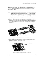
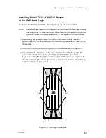
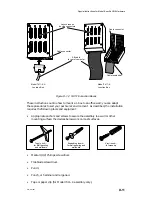
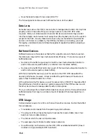
1. After you configure the board as described in Chapter 2, lay it on a static-free
surface with the junction box assembly(ies) you plan to install. See Figure D–4.
Lay out the assembly to avoid working over, and possibly damaging, the board
components.
J-box
VAC/16
Ribbon cable
Figure D–4 Model 7411–K VAC/16 and J-Box Assembly
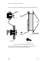
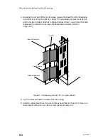
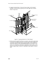
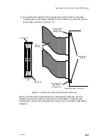
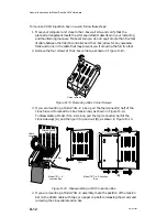
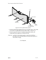
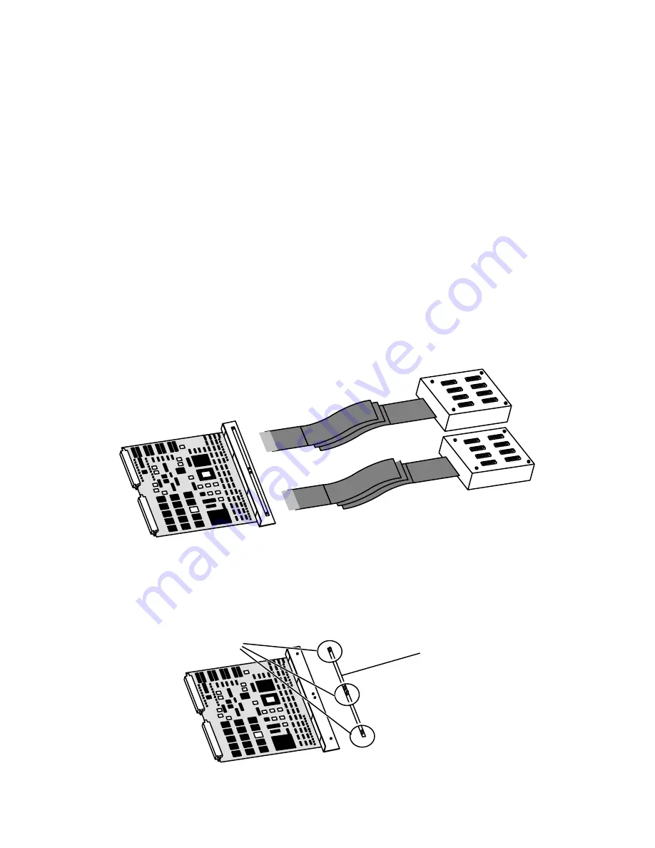
2. Remove the four screws holding the cable tension bar to the VAC/16 air dam;
then remove the tension bar. See Figure D–5.
Tension bar
Screws
Figure D–5 Removing the VAC/16 Cable Tension Bar
Summary of Contents for AViiON 5000 Series
Page 2: ......
Page 6: ......
Page 12: ...Preface x 014 001867 ...
Page 86: ...Configuring VME Option Boards 2 52 014 001867 ...
Page 144: ...Connecting External Devices to VME Option Boards 4 44 014 001867 ...
Page 150: ...VME Backplane Connector Signals and Power Distribution A 6 014 001867 ...
Page 196: ...Assigning VME Data Bus and Interrupt Priorities E 10 014 001867 ...
Page 206: ......
Page 210: ...Appendix Title ...

