External Device Connector Pin Assignments
C-5
014–001867
NOTE:
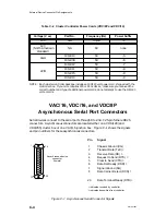
VAC/16, VDA/128, and VDA/255 boards are factory-configured as Data
Communications Equipment (DCE). The female device connectors on
your junction and cluster boxes are also DCE.
VAC/16 controllers connect to their 8-port junction boxes through a
data-transmission cable with either 64- or 68-pin connectors at either end.
The signals and pin assignments for these connectors are identical except
for the last four pins of the 68-pin connector, which are not used. Refer to
the HPS VMEbus Multiplexer (HPS-6236/6237) Technical Manual for
detailed information.
VDC/8P Parallel Port Connector
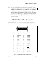
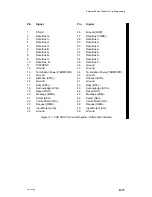
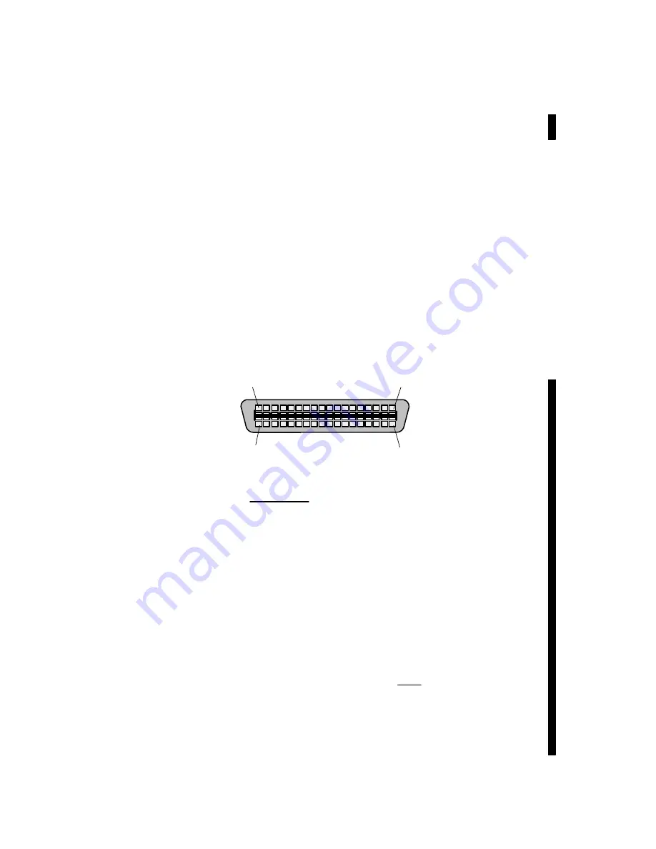
Parallel printers connect to the system through 36-pin connectors located on the
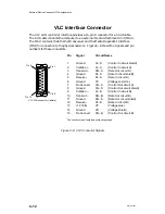
back of VDC/8P controller boxes. Figure C–2 shows the signals and pin numbers for
parallel printer connectors.
1
Data Strobe
2
Data 1
3
Data 2
4
Data 3
5
Data 4
6
Data 5
7
Data 6
8
Data 7
9
Data 8
10
Acknowledge
11
Not used
12
Paper Empty
13
Select
14
Not used
15
Not used
16
Not used
17
Not used
18
Not used
19
Ground
20
Ground
21
Ground
22
Ground
23
Ground
24
Ground
25
Ground
26
Ground
27
Ground
28
Ground
29
Ground
30
Not used
31
Not used
32
Fault
33
Ground
34
Not used
35
Not used
36
Not used
Pin Signal
Pin Signal
19
18
36
1
Figure C–2 VDC/8P Parallel Printer Connector Signals
Summary of Contents for AViiON 5000 Series
Page 2: ......
Page 6: ......
Page 12: ...Preface x 014 001867 ...
Page 86: ...Configuring VME Option Boards 2 52 014 001867 ...
Page 144: ...Connecting External Devices to VME Option Boards 4 44 014 001867 ...
Page 150: ...VME Backplane Connector Signals and Power Distribution A 6 014 001867 ...
Page 196: ...Assigning VME Data Bus and Interrupt Priorities E 10 014 001867 ...
Page 206: ......
Page 210: ...Appendix Title ...

