Connecting External Devices to VME Option Boards
4-11
014–001867
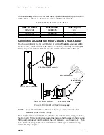
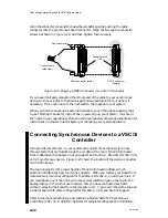
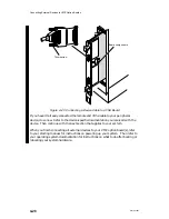
Pins
Slots
Ring
VDA/128 or
VDA/255
Air dam
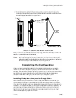
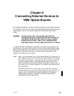
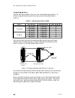
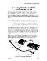
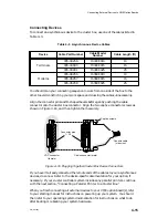
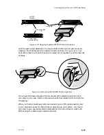
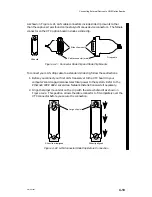
Figure 4–11 Attaching a BNC Host Connector to a VDA/128 or VDA/255 Receptacle
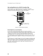
Connecting Asynchronous Devices to a Cluster Box
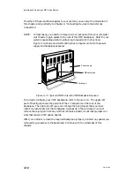
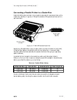
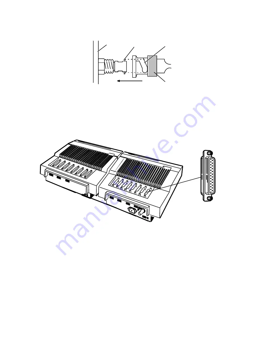
Each terminal or modem line on a cluster box can support any RS–232–C
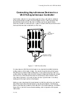
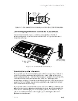
asynchronous device. Figure 4–12 shows the location of the asynchronous device
connectors on the box.
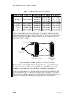
Terminal or modem
connectors (female)
Cluster box (16-line)
rear view
Figure 4–12 Cluster Box Device Connectors
Recording Device Line Information
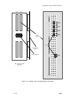
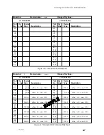
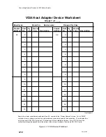
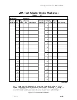
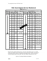
If your system uses the DG/UX operating system, fill out a copy of the worksheet in
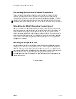
Figure 4–13 as you connect external devices to your cluster boxes. (Figure 4–15
shows a sample worksheet.) Use more than one page if necessary. You will need the
information recorded on the worksheets later, when your operating system
documentation directs you to set device characteristics such as baud rate and parity.
Leave the “tty Line” column on your device worksheet blank. Appendix B contains
extra worksheets that you can copy.
If your system will run DG/UX Release 4.30 or one of its updates, see Installing and
Setting Up the DG/UX
System on Stand-Alone Multiuser AViiON
Computers for
information on determining tty lines and specifying device characteristics. If your
system will run DG/UX Release 5.40 or higher, see Customizing the DG/UX
System for this information.
Summary of Contents for AViiON 5000 Series
Page 2: ......
Page 6: ......
Page 12: ...Preface x 014 001867 ...
Page 86: ...Configuring VME Option Boards 2 52 014 001867 ...
Page 144: ...Connecting External Devices to VME Option Boards 4 44 014 001867 ...
Page 150: ...VME Backplane Connector Signals and Power Distribution A 6 014 001867 ...
Page 196: ...Assigning VME Data Bus and Interrupt Priorities E 10 014 001867 ...
Page 206: ......
Page 210: ...Appendix Title ...

