background image

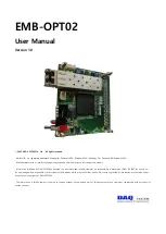
EMB-OPT02 

User Manual 

Version 1.0 


ⓒ 

2005 DAQ SYSTEM Co., Ltd.    All rights reserved.


Microsoft® is a registered trademark; Windows®, Windows NT®, Windows XP®, Windows 7®, Windows 8®, Windows 10® 
All other trademarks or intellectual property mentioned herein belongs to their respective owners. 


Information furnished by DAQ SYSTEM is believed to be accurate and reliable, However, no responsibility is assumed by DAQ SYSTEM for its use, nor 

for any infringements of patents or other rights of third parties which may result from its use. No license is granted by implication or otherwise under 
any patent or copyrights of DAQ SYSTEM. 
 

The information in this document is subject to change without notice and no part of this document may e copied or reproduced  without the prior 

written consent. 


Summary of Contents for EMB-OPT02

Page 1: ...n furnished by DAQ SYSTEM is believed to be accurate and reliable However no responsibility is assumed by DAQ SYSTEM for its use nor for any infringements of patents or other rights of third parties w...

Page 2: ...ontents 1 EMB OPT02 Introduction 2 2 EMB OPT02 Function 4 2 1 J1 Connector 5 2 2 JP1 Connector 7 2 3 SW1 Switch 7 2 4 SW3 Switch 8 2 5 CN1 SFP Connector 8 2 7 Fiber Cable 10 Appendix A 1 Board Size 12...

Page 3: ...t receiving board 1 Base Camera Link configuration is supported Figure 1 1 EMB OPT02 PCIe OPT02 Connection Reference The most important factor in selecting an optical cable is the communication distan...

Page 4: ...EMB OPT02 User s Manual 3 Fiber Cable Connection Caution Be careful not to twist the cable when connecting it to the SFP cage...

Page 5: ...tput 3 U2 FPGA 4 CN1 SFP Small Form Factor Pluggable Connector 5 U4 Serial Memory 6 JP1 12V Circular DC Jack 7 SW2 12V Power Switch 8 SW3 Connection mode selection switch The LED shows the inner worki...

Page 6: ...Digital In Out Data 6 10 DIO_IN7 Digital In Out Data 7 11 DIO_IN8 Digital In Out Data 8 12 DIO_IN9 Digital In Out Data 9 13 DIO_IN10 Digital In Out Data 10 14 DIO_IN11 Digital In Out Data 11 15 DIO_I...

Page 7: ...O_IN36 GPIO04 42 DIO_IN37 GPIO05 43 DIO_IN38 GPIO06 44 DIO_IN39 GPIO07 45 DIO_IN40 GPIO08 46 DIO_IN41 GPIO09 47 DIO_IN42 GPIO10 48 DIO_IN43 GPIO11 49 DIO_IN44 GPIO12 50 DIO_IN45 GPIO13 51 DIO_IN46 GPI...

Page 8: ...L I2C Serial Clock 2 2 JP1 Connector This is an external 12V DC Jack power connector HR10 7R 6S RA Figure 2 3 Rated power 2 3 SW1 Switch It is an option select switch SWITCH 3 OFF Vsync ON Reverse Vsy...

Page 9: ...ransmission Transceiver device The SFP transceiver is designed to support various optical transmissions such as SONET Gigabit Ethernet and Fiber Channel It supports hot pluggable transceiver and can b...

Page 10: ...gh Bandwidth 8 LOS When high indicates received optical power below worst case receiver sensitivity 9 RS1 Tx Rate Select Open or Low 2 125 or 4 25 Gb s Fibre Channel Low Bandwidth High 8 5 Gb s Fibre...

Page 11: ...it a large amount of information because the cable passage is narrow but instead it can be transmitted over a long distance The cable color is mainly yellow Multi Mode The core diameter is 50 100 so i...

Page 12: ...EMB OPT02 User s Manual 11 1 Single Mode LC Type 2 Multi Mode LC Type Figure 2 7 Cable type according to transmission mode...

Page 13: ...EMB OPT02 User s Manual 12 Appendix A 1 Board Size The external sizes of the board are as follows 65 x 69mm Top View 69 65...

Page 14: ...nty period repairs are charged in the following cases Failure or damage caused by use without following the user s manual Failure or damage caused by customer s negligence during product transportatio...

Page 15: ...EMB OPT02 User s Manual 14 MEMO Contact Point Web sit https www daqsystem com Email postmaster daqsystem com...

Reviews: