46
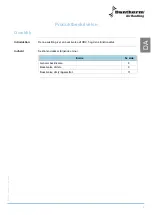
Wiring diagram
Introduction
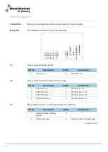
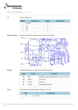
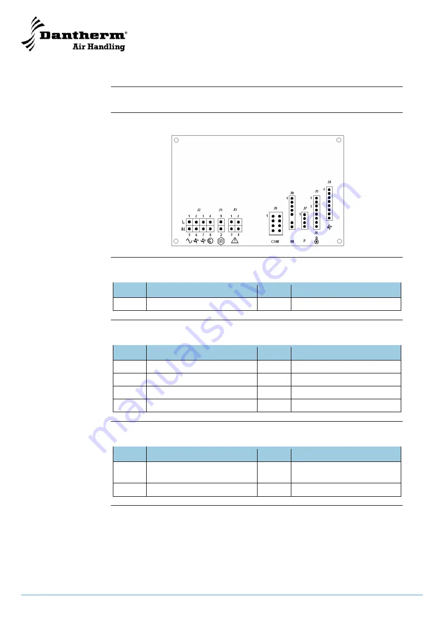
This section contains the electrical wiring diagrams for the main parts:
Main parts
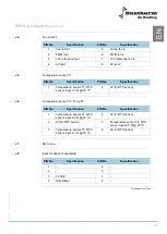
This illustrates the various pins for the main parts
J1
Power supply to heating element:
PIN No.
Specification
PIN No.
Specification
1
230 VAC
– L
2
230 VAC
– N
J2
Power supply in and lout to fans and rotor motor:
PIN No.
Specification
PIN No.
Specification
1
230 VAC In
– L
5
230 VAC In
– N
2
230 VAC Fan 1
– L
6
230 VAC Fan 1
– N
3
230 VAC Fan 2
– L
7
230 VAC Fan 2
– N
4
230 VAC Rotor
– L
8
230 VAC Rotor
– N
J3
Relay outlet for failure
– Contact specification: 5 A, 240 VAC:
PIN No.
Specification
PIN No.
Specification
1
Failure contact, normally
closed
3
-
2
Failure common
4
Failure contact, normally open
Continued overleaf
Summary of Contents for HRV 5
Page 1: ...Focus Trust Initiative HRV 5 Service manual DA GB DE No 039994 rev 2 0 08 03 2011...
Page 2: ...2005 layout...
Page 3: ...HRV 5 Service manual EN DA DE No 039994 rev 2 0 08 03 2011...
Page 54: ...52...
Page 104: ...52...
Page 138: ...36 Fortsetzung auf der n chsten Seite...
Page 148: ...46 Abmessungen Abbildung Die Abbildung zeigt die Abmessungen eines HRV 5...
Page 154: ...52 Firmenstempel Datum und Unterschrift...
Page 157: ...2005 layout...

