23
23
Danfoss District Energy
VI.GP.P1.02
DKDHR
Instructions
VX Solo II
8.0 Filling, Start-up
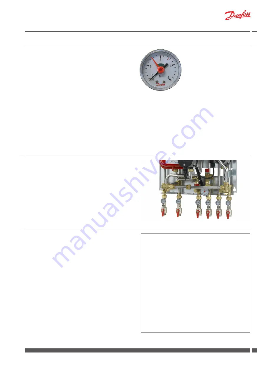
9.0 Manometer and filling
10.0 Electrical connections
Controller ECL 210/310
Supply voltage:
230 V a.c. - 50 Hz
Voltage range:
207 bis 244 V a.c. (IEC 60038)
Power consumption
5 VA
Load on relay outputs:
4(2) A - 230 V a.c
Load on triac outputs:
0,2 A - 230 V a.c.
Actuator AMV10 / AMV13 / AMV 150
Supply voltage:
230 V a.c. - 50 Hz
Power consumption:
2 / 7 VA
For further information please refer to the enclosed instructions.
Pump(s) (Alpha2 L)
Supply voltage:
230 V a.c. - 50 Hz
Protection class:
IP42
Power consumption:
Max. 25 Watt
(UPS pump max. 45 Watt)
For further information please refer to the enclosed installation and
operating instructions for the pump(s).
Check and tighten all connections before adding water to the system,
as vibrations during transport may have caused leaks.
After having added water to the system, tighten all the connections
before performing leak test.
Then heat up the system and tighten the connections once again.
Before adding water to the system and first start-up, check if:
- pipes are connected according to the circuit diagram,
- expansion vessel, if any, is connected,
- heat meter is mounted,
- shut-off valves are closed,
- threaded and flanged connections are tightened.
Adding water to the system:
1. Pump must be switched off when water is added to the system.
2. Fill heat exchanger and system with water until the manometer
shows a working pressure, which corresponds to the system
5 m (approx. 1.5 - 2.0 bar)
3. Deaerate the system completely.
4. Start the pump.
If the pressure drops below 1 bar, water must be added to the system.
The operating pressure should never exceed 2.5 bar.
(The safety valves open at 3 bar)
If system pressure drops dramatically within a short time, heating
system should be examined for leakage, - this includes checking
the factory set pressure of the expansion vessel.
Note;
Filling of water to the heating system must be done outside the
substation.
The station is wired and tested in the factory.
Electrical connections between the controller, pump (s), sensor and
actuator (s) are made.
The electrical connection of the substation must be performed by a
qualified and authorised electrician in compliance with all applicable
rules and regulations.
The station should be connected to a 230 V AC power supply.
Connection of power supply must be established in accordance with
current regulations and local standards.
The station must be wired and connected to an external main switch
so that it can be turned off during maintenance, cleaning or repair
work.


