Page
41
of
73
M-AI-VT-001-EN Rev.C.1
Options and Accessories
Drive Module Cooling
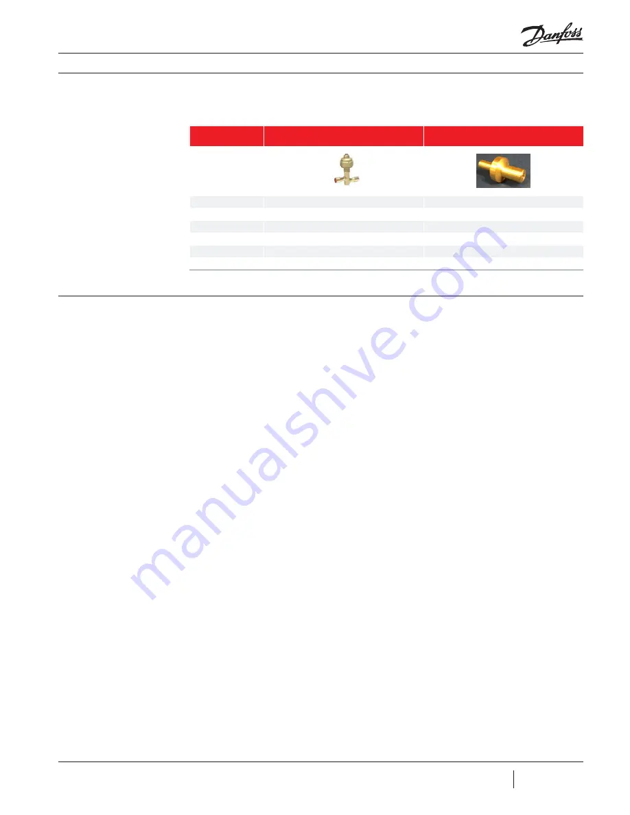
Tables 18 and 19 provide a list of components
that are required for use with the VTT compressor
EEV_P Pressure Regulator
Orifice
Item
Location
Drive Module Cooling Exit Line
*Drive Module Cooling Inlet Line
Function
Temperature Regulator
Flow Control
Model
ETS25
Inlet, mm (in.)
16 mm (5/8 in.) Female
12.5 mm (1/2") OD, Male
Outlet mm (in.)
16 mm (5/8 in.) Female
9.3 mm (3/8") OD, Male
Remarks
Factory Supplied
Factory Supplied
Table 18
Drive Module Cooling
Components
Ancillary Devices
A check valve shall be installed in the discharge
line of the compressor to protect against
backflow of refrigerant during coast down
even on single compressor chiller systems.
It is recommended that the valve be located
after a properly designed discharge cone
adaptor, preferably close to the condenser in
the packaged system. The check valve should
have a diameter no less than the minimum
recommended discharge pipe diameter specified
in table? Pressure drop in the discharge line and
check valve can have a dramatic negative impact
on efficiency, particularly at full load conditions,
so selecting a valve with a low pressure drop will
provide the highest full load efficiency. The check
valve should also have a low crack open pressure
and close instantly upon loss of flow.
An OEM supplied and actuated isolation valve
and control wiring must be installed in the
liquid refrigerant cooling line upstream of both
the drive and compressor. This valve is used to
prevent liquid migration when the compressor
is idle.
An OEM supplied and actuated isolation valve
and control wiring must be installed in the
economizer vapor line if the vapor line has a
connection to an economizer which shares a
vapor connection with another compressor.
This valve is used to prevent reverse rotation,
vapor bypass, and liquid migration during
and when the compressor is idle. As with the
other compressor lines, care should be taken
to minimize pressure drop in the economizer
vapor line and isolation valve to obtain maximum
economizer effectiveness. As an option, the
isolation valve may be installed in the liquid
line of a brazed plate style economizer if it does
not share a vapor connection with another
compressor.
Both the motor/drive cooling and economizer
isolation valves can be controlled through an
OEM relay which can receive a signal from pins
2&3 of the CIM board status plug. Alternatively,
the OEM system controller can read the status
of the output and activate the isolation valves
based on the output logic. Reference the
Programming and Operations manual to identify
the appropriate register.
*Note: this component is shipped loose and must be installed by the OEM.


