background image

1

[OK]: The first parameter in the group is shown.

2

Press [

] repeatedly to move down to the parameter.

3

Press [OK] to start editing.

4

[

]: First digit flashing (can be edited).

5

[

]: Second digit flashing (can be edited).

6

[

]: Third digit flashing (can be edited).

7

[

]: Decreases the parameter value, the decimal point

changes automatically.

8

[

]: Increases the parameter value.

9

[Back]: Cancel changes, return to 2.
[OK]: Accept changes, return to 2.

10 [

][

]: Select parameter within the group.

11 [Back]: Removes the value and shows the parameter group.
12 [

][

]: Select group.

Table 3.5 Changing Values in Continuous Parameters

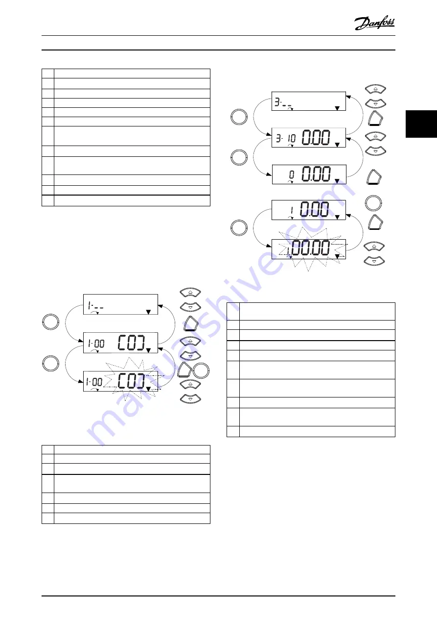
For enumerated parameters, the interaction is similar, but
the parameter value is shown in brackets because of the
digits limitation (4 large digits) on NLCP, and the enum can
be greater than 99. When the enum value is greater than
99, the LCP can only show the first part of the bracket.

130BC447.11

Setup 1

Setup 1

Setup 1

1

2

3

4

5

6

OK

OK

Back

7

OK

Back

Illustration 3.6 Main Menu Interactions - Enumerated
Parameters

1

[OK]: The first parameter in the group is shown.

2

Press [OK] to start editing.

3

[

][

]: Change parameter value (flashing).

4

Press [Back] to cancel changes or [OK] to accept changes
(return to screen 2).

5

[

][

]: Select a parameter within the group.

6

[Back]: Removes the value and shows the parameter group.

7

[

][

]: Select a group.

Table 3.6 Changing Values in Enumerated Parameters

Array parameters function as follows:

130BC448.10

1

2

4

5

6

7

8

9

10

OK

Back

Back

Back

5 x

Setup 1

Setup 1

Setup 1

Setup 1

%

INDEX

%

INDEX

%

INDEX

Setup 1

INDEX

%

OK

OK

OK

Illustration 3.7 Main Menu Interactions - Array Parameters

1

[OK]: Shows parameter numbers and the value in the first
index.

2

[OK]: Index can be selected.

3

[

][

]: Select index.

4

[OK]: Value can be edited.

5

[

][

]: Change parameter value (flashing).

6

[Back]: Cancels changes.
[OK]: Accepts changes.

7

[Back]: Cancels editing index, a new parameter can be
selected.

8

[

][

]: Select parameter within the group.

9

[Back]: Removes parameter index value and shows the
parameter group.

10 [

][

]: Select group.

Table 3.7 Changing Values in Array Parameters

Programming

Programming Guide

MG07C102

Danfoss A/S © 12/2015 All rights reserved.

17

3

3

Summary of Contents for VLT Midi Drive FC 280

Page 1: ...Programming Guide VLT Midi Drive FC 280 vlt drives danfoss com ...

Page 2: ......

Page 3: ...arameters 7 Controllers 66 4 9 Parameters 8 Communications and Options 70 4 10 Parameters 9 PROFIdrive 75 4 11 Parameters 10 CAN Fieldbus 81 4 12 Parameters 12 Ethernet 82 4 13 Parameters 13 Smart Logic Control 85 4 14 Parameters 14 Special Functions 91 4 15 Parameters 15 Drive Information 97 4 16 Parameters 16 Data Readouts 99 4 17 Parameters 18 Data Readouts 2 104 4 18 Parameters 21 Ext Closed L...

Page 4: ...arameter Lists 113 5 1 Introduction 113 5 2 Parameter Lists 116 6 Troubleshooting 133 6 1 Warnings and Alarms 133 Index 139 Contents VLT Midi Drive FC 280 2 Danfoss A S 12 2015 All rights reserved MG07C102 ...

Page 5: ...able 1 1 shows the document version and the corresponding software version Edition Remarks Software version MG07C1 The first version 1 0 Table 1 1 Document and Software Version AC Alternating current AEO Automatic energy optimization ACP Application control processor AWG American wire gauge AMA Automatic motor adaptation C Degrees Celsius DC Direct current EEPROM Electrically erasable programmable...

Page 6: ... motor with LCP and digital inputs Functions are divided into 2 groups Functions in group 1 have higher priority than functions in group 2 Group 1 Precise stop coast stop precise stop and coast stop quick stop DC braking stop and OFF Group 2 Start pulse start reversing start reversing jog and freeze output Table 1 3 Function Groups 1 2 3 Motor Motor running Torque generated on the output shaft and...

Page 7: ...V DC Analog outputs The analog outputs can supply a signal of 0 20 mA or 4 20 mA Automatic motor adaptation AMA The AMA algorithm determines the electrical parameters for the connected motor at standstill Brake resistor The brake resistor is a module capable of absorbing the brake power generated in regenerative braking This regenerative brake power increases the intermediate circuit voltage and a...

Page 8: ...Acronym describing the switching pattern stator flux oriented asynchronous vector modulation Slip compensation The frequency converter compensates for the motor slip by giving the frequency a supplement that follows the measured motor load keeping the motor speed almost constant Smart logic control SLC The SLC is a sequence of user defined actions executed when the associated user defined events a...

Page 9: ...V DC 0 10 V DC 24 V DC 02 01 24 V NPN 0 V PNP 0 V PNP 24 V NPN 19 D IN 24 V NPN 0 V PNP 27 D IN OUT 24 V 0 V 0 V PNP 24 V NPN 29 D IN 24 V NPN 0 V PNP 0 V PNP 24 V NPN 33 D IN 32 D IN 38 D IN 37 D IN 95 P 5 00 2 1 ON DC R 89 BR 81 0 10 V DC DC 88 RFI 0 V 250 V AC 3 A Relay 1 Illustration 1 2 Basic Wiring Schematic Drawing A Analog D Digital Built in brake chopper is only available on 3 phase units...

Page 10: ...DC PNP Source Digital input wiring Illustration 1 3 PNP Source NPN Sink Digital input wiring 12 13 18 19 27 29 32 33 55 24 VDC 0 VDC 130BE731 10 Illustration 1 4 NPN Sink NOTICE Control cables must be shielded armoured See the section Using Shielded Control Cables in the design guide for the correct termination of control cables 130BA681 10 Illustration 1 5 Grounding of Shielded Armoured Control C...

Page 11: ... Digital Input 21 Speed up Terminal 32 parameter 5 14 Terminal 32 Digital Input 22 Speed down FC 24 V D IN D IN D IN D IN D IN D IN D IN 10 V A IN A IN COM A OUT 12 18 19 27 29 32 33 31 50 53 54 55 42 130BD069 11 Illustration 1 8 Speed Up Down 1 3 5 Potentiometer Reference Voltage reference via a potentiometer Reference source 1 1 Analog input 53 default Terminal 53 low voltage 0 V Terminal 53 hig...

Page 12: ...onverter is connected to AC mains DC supply or load sharing the motor may start at any time Unintended start during programming service or repair work can result in death serious injury or property damage The motor can start with an external switch a fieldbus command an input reference signal from the LCP via remote operation using MCT 10 Set up Software or after a cleared fault condition To preve...

Page 13: ...ith rotating shafts and electrical equipment can result in death or serious injury Ensure that only trained and qualified personnel perform installation start up and maintenance Ensure that electrical work conforms to national and local electrical codes Follow the procedures in this guide CAUTION INTERNAL FAILURE HAZARD An internal failure in the frequency converter can result in serious injury wh...

Page 14: ...set up If the same set up acts as both active and edit set up only that set up number is shown factory setting When active and edit set up differ both numbers are shown in the display for example set up 12 The number flashing indicates the edit set up 2 Parameter number 3 Parameter value 4 Motor direction is shown in the bottom left of the display A small arrow indicates the direction 5 The triang...

Page 15: ...LECTRICAL HAZARD Even after pressing the Off Reset key voltage is present at the terminals of the frequency converter Pressing the Off Reset key does not disconnect the frequency converter from mains Touching live parts can result in death or serious injury Do not touch any live parts 3 1 2 The Right key Function on NLCP Press to edit any of the 4 digits on the display individually When pressing o...

Page 16: ...ither QM1 or QM2 then press OK 3 Press to browse through the parameters in Quick Menu 4 Press OK to select a parameter 5 Press to change the value of a parameter setting 6 Press OK to accept the change 7 To exit press either Back twice or 3 times if in QM2 and QM3 to enter Status or press Menu once to enter Main Menu Programming VLT Midi Drive FC 280 14 Danfoss A S 12 2015 All rights reserved MG07...

Page 17: ...24 XXXX A 1 20 XXXX kW 1 22 XXXX V Motor nominal speed PM Motor Asynchronous Motor Motor power Motor voltage Motor Cont Rated Torque 1 26 XXXX 1 23 XXXX Hz Stator Resistance Motor frequency 1 25 XXXX rpm Rs 1 30 XXXX 1 40 XXXX 1 37 XXXX 1 25 XXXX rpm 1 24 XXXX A Motor Current Motor Poles Back EMF at 1000 RPM d axis Inductance Ld 1 39 XXXX 4 19 XXXX Hz 4 14 XXXX Hz Stator Resistance Rs Motor Poles ...

Page 18: ...ice or 3 times for array parameters to enter Main Menu or press Menu once to enter Status See Illustration 3 5 Illustration 3 6 and Illustration 3 7 for the principles of changing the value of continuous enumerated and array parameters respectively The actions in the illustrations are described in Table 3 5 Table 3 6 and Table 3 7 130BC446 10 Setup 1 Setup 1 Setup 1 Setup 1 Setup 1 Setup 1 Setup 1...

Page 19: ...6 Main Menu Interactions Enumerated Parameters 1 OK The first parameter in the group is shown 2 Press OK to start editing 3 Change parameter value flashing 4 Press Back to cancel changes or OK to accept changes return to screen 2 5 Select a parameter within the group 6 Back Removes the value and shows the parameter group 7 Select a group Table 3 6 Changing Values in Enumerated Parameters Array par...

Page 20: ...ons and many detailed application instructions 8 Main Menu Allows access to all programming parameters 9 Alarm Log Shows a list of current warnings the last 10 alarms and the maintenance log Table 3 9 Legend to Illustration 3 8 Display Menu Keys C Navigation keys and indicator lights LEDs Navigation keys are used for programming functions and moving the display cursor The navigation keys also prov...

Page 21: ...e parameters press OK to select a parameter 4 Press to change the value of a parameter setting 5 Press to shift digit when a decimal parameter is in the editing state 6 Press OK to accept the change 7 Press either Back twice to enter Status or press Main Menu once to enter the Main Menu View changes Quick Menu Q5 Changes Made lists all parameters changed from default settings The list only shows p...

Page 22: ...ypically not available on the motor nameplate Run a complete AMA using parameter 1 29 Automatic Motor Adaptation AMA 1 Enable Complete AMA or enter the parameters manually 1 Parameter 1 30 Stator Resistance Rs 2 Parameter 1 31 Rotor Resistance Rr 3 Parameter 1 33 Stator Leakage Reactance X1 4 Parameter 1 35 Main Reactance Xh Application specific adjustment when running VVC VVC is the most robust c...

Page 23: ...C PM settings Table 3 13 shows recommendations in different applications Application Settings Low inertia applications ILoad IMotor 5 Increase the value for parameter 1 17 Voltage filter time const by factor 5 10 Reduce the value for parameter 1 14 Damping Gain Reduce the value 100 for parameter 1 66 Min Current at Low Speed Medium inertia applications 50 ILoad IMotor 5 Keep calculated values High...

Page 24: ...cable length in parameter 1 42 Motor Cable Length 7 Go to parameter 1 29 Automatic Motor Adaptation AMA 8 Press OK 9 Select 1 Enable complete AMA 10 Press OK 11 The test runs automatically and indicates when it is complete Depending on the power size the AMA takes 3 to 10 minutes to complete NOTICE The AMA function does not cause the motor to run and it does not harm the motor Programming VLT Midi...

Page 25: ...e Select the supply voltage frequency and type Option Function 10 380 440V 50Hz IT grid 11 380 440V 50Hz Delta 12 380 440V 50Hz 20 440 480V 50Hz IT grid 0 06 GridType Select the supply voltage frequency and type Option Function 21 440 480V 50Hz Delta 22 440 480V 50Hz 100 200 240V 60Hz IT grid 101 200 240V 60Hz Delta 102 200 240V 60Hz 110 380 440V 60Hz IT grid 111 380 440V 60Hz Delta 112 380 440V 6...

Page 26: ...alue 1609 Custom Readout 1610 Power kW 1611 Power hp 1612 Motor Voltage 1613 Frequency 1614 Motor current 0 20 Display Line 1 1 Small Select a variable to display in line 1 left position Option Function 1615 Frequency 1616 Torque Nm 1618 Motor Thermal 1620 Motor Angle 1622 Torque 1630 DC Link Voltage 1633 Brake Energy 2 min 1634 Heatsink Temp 1635 Inverter Thermal 1636 Inv Nom Current 1637 Inv Max...

Page 27: ...rent 1615 Frequency 1616 Torque Nm 1618 Motor Thermal 1620 Motor Angle 1622 Torque 0 21 Display Line 1 2 Small Select a variable to display in line 1 middle position Option Function 1630 DC Link Voltage 1633 Brake Energy 2 min 1634 Heatsink Temp 1635 Inverter Thermal 1636 Inv Nom Current 1637 Inv Max Current 1638 SL Controller State 1639 Control Card Temp 1650 External Reference 1652 Feedback Unit...

Page 28: ...al 1636 Inv Nom Current 0 22 Display Line 1 3 Small Select a variable to display in line 1 right position Option Function 1637 Inv Max Current 1638 SL Controller State 1639 Control Card Temp 1650 External Reference 1652 Feedback Unit 1653 Digi Pot Reference 1657 Feedback RPM 1660 Digital Input 1661 Terminal 53 Setting 1662 Analog Input 53 1663 Terminal 54 Setting 1664 Analog Input AI54 1665 Analog...

Page 29: ... Select a variable for display in line 2 Option Function 1653 Digi Pot Reference 1657 Feedback RPM 1660 Digital Input 1661 Terminal 53 Setting 1662 Analog Input 53 1663 Terminal 54 Setting 1664 Analog Input AI54 1665 Analog Output 42 mA 1666 Digital Output 1667 Pulse Input 29 Hz 1668 Pulse Input 33 Hz 1669 Pulse Output 27 Hz 1671 Relay Output 1672 Counter A 1673 Counter B 1674 Prec Stop Counter 16...

Page 30: ...63 Terminal 54 Setting 1664 Analog Input AI54 1665 Analog Output 42 mA 1666 Digital Output 1667 Pulse Input 29 Hz 1668 Pulse Input 33 Hz 1669 Pulse Output 27 Hz 1671 Relay Output 1672 Counter A 1673 Counter B 1674 Prec Stop Counter 1680 Fieldbus CTW 1 1682 Fieldbus REF 1 1684 Comm Option STW 1685 FC Port CTW 1 1686 FC Port REF 1 1690 Alarm Word 1691 Alarm Word 2 1692 Warning Word 1693 Warning Word...

Page 31: ...ssible to select a value different from 0 when selecting a linear unit in parameter 0 30 Custom Readout Unit For quadratic and cubic units the minimum value is 0 0 32 Custom Readout Max Value Range Function 100 Custom ReadoutUnit 0 0 999999 99 CustomRea doutUnit This parameter sets the maximum value to be shown when the motor speed has reached the value set for parameter 4 14 Motor Speed High Limi...

Page 32: ... Size indep from LCP Copies only the parameters that are independent of the motor size This selection can be used to program several frequency converters with the same function without disturbing motor data that is already set 0 51 Set up Copy Use this parameter to copy parameters between set ups Option Function 0 No copy 1 Copy from setup 1 2 Copy from setup 2 3 Copy from setup 3 4 Copy from setu...

Page 33: ... slip and load compensations 1 03 Torque Characteristics Option Function Select the torque characteristic required VT and AEO are both energy saving operations 0 Constant torque 1 Variable Torque 2 Auto Energy Optim CT 1 06 Clockwise Direction Option Function NOTICE This parameter cannot be adjusted while the motor is running This parameter defines the term clockwise corresponding to the LCP direc...

Page 34: ...7 kW 0 5 hp 6 0 55 kW 0 75 hp 7 0 75 kW 1 hp 8 1 1 kW 1 5 hp 9 1 5 kW 2 hp 10 2 2 kW 3 hp 11 3 kW 4 hp 12 3 7 kW 5 hp 13 4 kW 5 4 hp 14 5 5 kW 7 5 hp 15 7 5 kW 10 hp 1 20 Motor Power Option Function 16 11 kW 15 hp 17 15 kW 20 hp 18 18 5 kW 25 hp 19 22 kW 30 hp 20 30 kW 40 hp 21 37 kW 50 hp 22 45 kW 60 hp 23 55 kW 75 hp 24 75 kW 100 hp 25 90 kW 120 hp 26 110 kW 150 hp 1 22 Motor Voltage Range Funct...

Page 35: ...Main Reactance Xh If 1 PM non salient SPM non Sat is selected the AMA is performed on Parameter 1 30 Stator Resistance Rs Parameter 1 37 d axis Inductance Ld If 2 PM salient IPM non Sat is selected the AMA is performed on 1 29 Automatic Motor Adaption AMA Option Function Parameter 1 30 Stator Resistance Rs Parameter 1 37 d axis Inductance Ld Parameter 1 38 q axis Inductance Lq If 3 PM salient IPM ...

Page 36: ...equency converter from the motor nameplate data 1 35 Main Reactance Xh Range Function Size related 0 0 999 9 Ohm Set the main reactance of the motor using 1 of these methods Run an AMA on a cold motor The frequency converter measures the value from the motor Enter the Xh value manually Obtain the value from the motor supplier Use the Xh default setting The frequency converter establishes the setti...

Page 37: ...e default value If the motor supplier provides the saturation curve enter 1 45 q axis Inductance Sat LqSat Range Function the q axis inductance value which is 100 of the nominal current 1 46 Position Detection Gain Range Function 100 20 200 Adjusts the amplitude of the test pulse during position detection at start Adjust this parameter to improve the position measurement 1 48 Current at Min Induct...

Page 38: ...results in slow reaction and a low value results in quick reaction If low frequency resonance problems occur use a longer time setting 1 64 Resonance Dampening Range Function 100 0 500 Enter the resonance dampening value Set parameter 1 64 Resonance Dampening and parameter 1 65 Resonance Dampening Time Constant to help eliminate high frequency resonance problems To reduce resonance oscillation inc...

Page 39: ...eter 1 75 Start Speed Hz and the output current corresponds to the setting of the start current in parameter 1 76 Start Current This function is typically used in hoisting applications without counterweight and especially in applications with a Cone 1 72 Start Function Option Function motor where the start is clockwise followed by rotation in the reference direction 4 Horizontal operation Only pos...

Page 40: ...ax Speed Hz must not exceed the time set in this parameter Otherwise the frequency converter trips with alarm 18 Start Failed Any time set in parameter 1 71 Start Delay for use of a start function must be executed within the time limit 1 80 Function at Stop Option Function Select the frequency converter function after a stop command or after the speed is ramped down to the settings in 1 80 Functio...

Page 41: ...ermistor PTC sensor in the motor for winding protection 3 ETR warning 1 Calculates the load when set up 1 is active and activates a warning in the display when the motor is overloaded Program a warning signal via 1 of the digital outputs 4 ETR trip 1 Calculates the load when set up 1 is active and stops trips the frequency converter when the motor is overloaded Program a warning signal via 1 of th...

Page 42: ... Set current as percentage of rated motor current parameter 1 24 Motor Current 2 07 Parking Time Range Function 3 s 0 1 60 s Set the duration of the parking current set in parameter 2 06 Parking Current once activated 2 10 Brake Function Option Function 0 Off No brake resistor is installed 1 Resistor brake A brake resistor is incorporated in the system for dissipating surplus brake energy as heat ...

Page 43: ...rvoltage control OVC reduces the risk of the frequency converter tripping due to an overvoltage on the DC link caused by generative power from the load 0 Disabled No OVC required 1 Enabled not at stop Activates OVC except when using a stop signal to stop the frequency converter 2 Enabled Activates OVC 2 17 Over voltage Control Option Function WARNING PERSONAL INJURY AND EQUIPMENT DAMAGE Enabling O...

Page 44: ...nce Range Function 0 Reference Feedback Unit 0 4999 Reference Feedback Unit Enter the minimum reference The minimum reference is the lowest value obtainable by summing all references The minimum reference is active only when parameter 3 00 Reference Range is set to 0 Min Max The minimum reference unit matches The option in parameter 1 00 Configuration Mode The unit selected in parameter 3 01 Refer...

Page 45: ...Reference This results in the actual reference Z Actual reference X is the sum of the inputs selected in parameter 3 15 Reference 1 Source parameter 3 16 Reference 2 Source parameter 3 17 Reference 3 Source and parameter 8 02 Control Source Relative Z X X Y 100 Resulting actual reference Y X 130BA059 12 Z Illustration 4 3 Preset Relative Reference X 100 0 100 Z Y X X Y 100 P 3 14 130BA278 10 Illus...

Page 46: ...ency input 33 11 Local bus reference 3 40 Ramp 1 Type Option Function Select the ramp type depending on requirements for acceleration deceleration A linear ramp gives constant acceleration during ramping A sine 2 ramp gives non linear acceleration 0 Linear 1 Sine Ramp 2 Sine 2 Ramp S ramp based on the values set in parameter 3 41 Ramp 1 Ramp Up Time and parameter 3 42 Ramp 1 Ramp Down Time 3 41 Ra...

Page 47: ...wn 3 61 Ramp 3 Ramp up Time Range Function time in parameter 3 62 Ramp 3 Ramp down Time 3 62 Ramp 3 Ramp down Time Range Function Size related 0 05 3600 s Enter the ramp down time which is the deceleration time from the rated motor speed ns to 0 RPM Select a ramp down time such that no overvoltage arises in the inverter due to regenerative operation of the motor and such that the generated current...

Page 48: ...rative operation of the motor required to achieve the given ramp down time Ensure also that the generated current required to achieve the given ramp down time does not exceed the current limit set in parameter 4 18 Current Limit Activate quick 3 81 Quick Stop Ramp Time Range Function stop with a signal on a selected digital input or via the serial communication port 130BD376 10 Time Hz P 4 14 Hz h...

Page 49: ...DECREASE is activated 3 96 Maximum Limit Switch Reference Enter the maximum limit switch reference If the crane reaches a limit switch OFF and if the speed exceeds the value in this parameter then the speed is reduced automatically to the value in this parameter If the limit switch is off the speed cannot exceed the value in this parameter Range Function 25 0 200 Parameter Descriptions Programming...

Page 50: ...oversynchronous range However due to field weakening the motor torque at current limit drops accordingly when the voltage increase stops above the synchronized motor speed 4 19 Max Output Frequency Range Function Size related 0 500 Hz NOTICE This parameter cannot be adjusted while the motor is running NOTICE Maximum output frequency cannot exceed 10 of the inverter switching frequency parameter 14...

Page 51: ...50 Hz Select the maximum allowed error in speed output speed versus feedback Time sec Speed rpm ncalc nactual P 4 32 130BA221 10 P 4 31 Illustration 4 8 Motor Feedback Speed Error 4 32 Motor Feedback Loss Timeout Range Function 0 05 s 0 60 s Set the timeout value allowing the speed error set in parameter 4 31 Motor Feedback Speed Error to be exceeded before enabling the function selected in parame...

Page 52: ...9 ProcessCtrlUnit 4999 4999 ProcessCtrlUnit Use this parameter to set a low limit for the feedback range When the feedback drops below this limit the display shows Feedb Low Bit 6 is set in parameter 16 94 Ext Status Word The output relay or the digital output can be configured to indicate this warning The LCP warning light is not turned on when this parameter set limit is reached 4 57 Warning Fee...

Page 53: ...p by itself To ensure that the frequency converter stops configure a digital output to 27 Torque limit and stop and connect this digital output to a digital input that is configured as coast Stop inverted function Generates a stop function when the selected terminal goes from logic 1 to logic 0 The stop is performed according to the selected ramp time parameter 3 42 Ramp 1 Ramp Down Time parameter...

Page 54: ...by value 1 0 Increased by value 0 1 Reduced by value 1 1 Table 4 2 Shut Down Catch Up 22 Speed down Same as 21 Speed up 23 Set up select bit 0 Select 23 Set up select bit 0 or 1 Set up select bit 1 to select 1 of the 2 set ups Set parameter 0 10 Active Set up to 9 Multi Set up 24 Set up select bit 1 Default digital input 32 Same as 23 Set up select bit 0 26 Precise stop inv Precise stop inverse fu...

Page 55: ...ctive when parameter 37 00 Application Mode is set to 2 Position Control 160 Go To Target Pos The frequency converter moves to the target position This option is only effective when parameter 37 00 Application Mode is set to 2 Position Control 162 Pos Idx Bit0 Position index bit 0 This option is only effective when parameter 37 00 Application Mode is set to 2 Position Control 163 Pos Idx Bit1 Posi...

Page 56: ...Freq Low 17 Above frequency high The output speed is higher than the setting in parameter 4 41 Warning Freq High 18 Out of feedback range The feedback is outside the range set in parameter 4 56 Warning Feedback Low and parameter 4 57 Warning Feedback High 19 Below feedback low The feedback is below the limit set in parameter 4 56 Warning Feedback Low 20 Above feedback high The feedback is above th...

Page 57: ...E the output goes high Otherwise it is low 74 Logic Rule 4 See parameter group 13 4 Logic Rules If logic rule 4 is evaluated as TRUE the output goes high Otherwise it is low 75 Logic Rule 5 See parameter group 13 4 Logic Rules If logic rule 5 is evaluated as TRUE the output goes high Otherwise it is low 80 SL Digital Output A See parameter 13 52 SL Controller Action The output goes high whenever t...

Page 58: ...ver under voltage 25 Reverse 26 Bus OK 27 Torque limit stop 28 Brake no brake warning 29 Brake ready no fault 30 Brake fault IGBT 31 Relay 123 32 Mech brake ctrl 36 Control word bit 11 5 30 Terminal 27 Digital Output Option Function 37 Control word bit 12 40 Out of ref range 41 Below reference low 42 Above ref high 43 Extended PID Limit 45 Bus ctrl 46 Bus control timeout On 47 Bus control timeout ...

Page 59: ...Below frequency low The output frequency is lower than the setting in parameter 4 40 Warning Freq Low 17 Above frequency high The frequency is higher than the setting in parameter 4 41 Warning Freq High 18 Out of feedb range The feedback is outside the range set in parameter 4 56 Warning Feedback Low and parameter 4 57 Warning Feedback High 19 Below feedback low The feedback is below the limit set...

Page 60: ... 5 90 Digital Relay Bus Control When a bus timeout occurs the output state is set high on 47 Bus control timeout Off Controls output via bus The state of the output is set in 5 40 Function Relay Option Function parameter 5 90 Digital Relay Bus Control When a bus timeout occurs the output state is set low off 56 Heat sink cleaning warning high 60 Comparator 0 See parameter group 13 1 Smart Logic Co...

Page 61: ...ompleted This option is only effective when parameter 37 00 Application Mode is set to 2 Position Control 171 Target Position Reached The target position is reached This option is only effective when parameter 37 00 Application Mode is set to 2 Position Control 172 Position Control Fault A fault occurred in the positioning process Refer to parameter 37 18 Pos Ctrl Fault Reason for details about th...

Page 62: ...ion 0 4999 4999 Enter the low reference value limit for the motor shaft speed Hz This value is also the lowest feedback value see also parameter 5 57 Term 33 Low Ref Feedb Value Set terminal 29 to digital input parameter 5 02 Terminal 29 Mode 0 Input and parameter 5 13 Terminal 29 Digital Input applicable value 5 53 Term 29 High Ref Feedb Value Range Function Size related 4999 4999 Enter the high ...

Page 63: ...r shaft 1 Counter clockwise Sets channel A 90 electrical degrees ahead of channel B after clockwise rotation of the encoder shaft 5 90 Digital Relay Bus Control Range Function 0 0 0xFFFFFFFF This parameter holds the state of the digital outputs and relays controlled by bus A logical 1 indicates that the output is high or active A logical 0 indicates that the output is low or inactive Bit 0 3 Reser...

Page 64: ... Low Current Range Function 4 mA 0 20 mA Enter the low current value This reference signal corresponds to the low reference feedback value that is set in parameter 6 14 Terminal 53 Low Ref Feedb Value To activate parameter 6 01 Live Zero Timeout Function set the value to 2 mA 6 13 Terminal 53 High Current Range Function 20 mA 0 20 mA Enter the high current value corresponding to the high reference...

Page 65: ...rresponds to the high reference value set in parameter 6 25 Terminal 54 High Ref Feedb Value 6 22 Terminal 54 Low Current Range Function 4 mA 0 20 mA Enter the low current value This reference signal corresponds to the low reference feedback value set in parameter 6 24 Terminal 54 Low Ref Feedb Value To activate the live zero timeout function in parameter 6 01 Live Zero Timeout Function set the va...

Page 66: ...Below feedback low 6 92 Terminal 42 Digital Output Option Function 20 Above feedback high 21 Thermal warning 22 Ready no thermal warning 23 Remote ready no TW 24 Ready no over under voltage 25 Reverse 26 Bus OK 27 Torque limit stop 28 Brake no brake warning 29 Brake ready no fault 30 Brake fault IGBT 31 Relay 123 32 Mech brake ctrl 36 Control word bit 11 37 Control word bit 12 40 Out of ref range ...

Page 67: ... been detected See parameter group 22 4 Sleep Mode 198 Drive Bypass 6 93 Terminal 42 Output Min Scale Range Function 0 0 200 Scale for the minimum output 0 mA or 4 mA of the analog signal at terminal 42 Set the value to be the percentage of the full range of the variable selected in parameter 6 91 Terminal 42 Analog Output 6 94 Terminal 42 Output Max Scale Range Function 100 0 200 Scale for maximu...

Page 68: ...al to the rate 7 04 Speed PID Differentiation Time Range Function of change of the speed feedback The quicker the error changes the stronger the gain from the differentiator The gain is proportional with the speed at which errors change Setting this parameter to 0 disables the differentiator This parameter is used with parameter 1 00 Configu ration Mode 1 Speed closed loop control 7 05 Speed PID D...

Page 69: ...ting leads to controller instability 7 20 Process CL Feedback 1 Resource Option Function The effective feedback signal is made up of the sum of up to 2 different input signals Select which input is treated as the source of the first of these signals The 2nd input signal is defined in parameter 7 22 Process CL Feedback 2 Resource 0 No function 1 Analog Input 53 2 Analog Input 54 3 Frequency input 2...

Page 70: ... changes occur limit the differentiator gain 7 38 Process PID Feed Forward Factor Range Function 0 0 200 Enter the PID feed forward FF factor The FF factor sends a constant fraction of the reference signal to bypass the PID control so the PID control only affects the remaining fraction of the control signal Any change to this parameter affects the motor speed When the FF factor is activated it pro...

Page 71: ...the process PID controller 1 Enabled Enables the extended parts of the PID controller 7 51 Process PID Feed Fwd Gain Range Function 1 0 100 The feed forward is used to obtain the gain based on a well known signal available The PID controller then only takes care of the smaller part of the control necessary because of unknown characters The standard feed forward factor in parameter 7 38 Process PID...

Page 72: ...utput 2 Stop 3 Jogging 4 Max speed 5 Stop and trip 8 07 Diagnosis Trigger Option Function 0 Disable 1 Trigger on alarms 2 Trigger alarm warn 8 10 Control Word Profile Select the interpretation of the control and status words corresponding to the installed fieldbus Only the selections valid for the installed fieldbus are visible in the LCP display Option Function 0 FC profile 1 PROFIdrive profile 7...

Page 73: ...8 42 PCD Write Configuration Enter up to 16 different preset mapping 0 15 in this parameter using array programming If this parameter is active addresses 2810 2825 represent values of the 16 parameters If this parameter is not active addresses 2810 and 2811 are used as input data drive control word and bus reference Addresses 2812 2825 are reserved Option Function 9 412 Motor Speed Low Limit Hz 10...

Page 74: ... and or via the fieldbus NOTICE When parameter 1 10 Motor Construction is set to 1 PM non salient SPM only selection 0 Digital input is available 0 Digital input Activates start command via a digital input 1 Bus Activates start command via the serial communi cation port or fieldbus option 2 Logic AND Activates start command via the fieldbus serial communication port and additionally via 1 of the d...

Page 75: ...onverter OFF3 selection via the terminals digital input and or via the fieldbus This parameter is active only when parameter 8 01 Control Site is set to 0 Digital and ctrl word and parameter 8 10 Control Word Profile is set to 1 Profidrive profile Option Function 0 Digital input 1 Bus 8 58 Profidrive OFF3 Select Select control of the frequency converter OFF3 selection via the terminals digital inp...

Page 76: ...ctivated via the serial port or fieldbus option 8 91 Bus Jog 2 Speed Range Function 200 RPM 0 1500 RPM Enter the jog speed This value is a fixed jog speed activated via the serial port or fieldbus option Parameter Descriptions VLT Midi Drive FC 280 74 Danfoss A S 12 2015 All rights reserved MG07C102 4 4 ...

Page 77: ... Generator Mode 553 Term 29 High Ref Feedb Value 558 Term 33 High Ref Feedb Value 590 Digital Relay Bus Control 593 Pulse Out 27 Bus Control 615 Terminal 53 High Ref Feedb Value 9 15 PCD Write Configuration Option Function 625 Terminal 54 High Ref Feedb Value 696 Terminal 42 Output Bus Control 748 PCD Feed Forward 890 Bus Jog 1 Speed 891 Bus Jog 2 Speed 1680 Fieldbus CTW 1 1682 Fieldbus REF 1 3401...

Page 78: ...Address Range Function 126 0 126 Enter the station address in this parameter or alternatively in the hardware switch To adjust the station address in parameter 9 18 Node Address set the hardware switch to 126 or 127 that is all switches set to on Otherwise this parameter shows the actual setting of the switch 9 19 Drive Unit System Number Range Function 1037 0 65535 Manufacturer specific system ID...

Page 79: ...e For Application 3402 PCD 2 Write For Application 3403 PCD 3 Write For Application 3404 PCD 4 Write For Application 3405 PCD 5 Write For Application 3406 PCD 6 Write For Application 3407 PCD 7 Write For Application 3408 PCD 8 Write For Application 3409 PCD 9 Write For Application 3410 PCD 10 Write For Application 3421 PCD 1 Read For Application 3422 PCD 2 Read For Application 3423 PCD 3 Read For ...

Page 80: ...0 65535 This parameter shows PROFIBUS communication warnings Bit Description 0 Connection with DP master is lost 1 Not used 2 FDL fieldbus data link layer is not OK 3 Clear data command received 4 Actual value is not updated 5 Baud rate search 6 PROFIBUS ASIC is not transmitting 7 Initializing of PROFIBUS is not OK 8 Frequency converter is tripped 9 Internal CAN error 10 Wrong configuration data f...

Page 81: ...n Function Parameter values changed via RS485 are not automatically stored in a non volatile memory Use this parameter to activate a function that stores parameter values in the EEPROM non volatile memory so changed parameter values are retained at power down 0 Off Deactivates the non volatile storage function 1 Store all setups Stores all parameter values in the set up selected in parameter 9 70 ...

Page 82: ...hows a list of all the frequency converter parameters deviating from default setting 9 91 Changed Parameters 2 Range Function 0 0 9999 This parameter shows a list of all the frequency converter parameters deviating from default setting 9 92 Changed Parameters 3 Range Function 0 0 9999 This parameter shows a list of all the frequency converter parameters deviating from default setting 9 93 Changed ...

Page 83: ...e ID Range Function 127 1 127 10 05 Readout Transmit Error Counter Range Function 0 0 255 10 06 Readout Receive Error Counter Range Function 0 0 255 10 31 Store Data Values Option Function 0 Off 2 Store all setups 3 Store edit setup 10 33 Store Always Option Function 0 Off 1 On Parameter Descriptions Programming Guide MG07C102 Danfoss A S 12 2015 All rights reserved 81 4 4 ...

Page 84: ...me servers Can be automatically assigned when using DHCP 12 07 Domain Name Range Function 0 0 48 Domain name of the attached network Can be automatically assigned when using DHCP network 12 08 Host Name Range Function 0 0 48 Logical given name of option 12 09 Physical Address Range Function 0 0 17 Read only Shows the physical MAC address of the option 12 10 Link Status Option Function 0 No Link 1 ...

Page 85: ...hich detects common cabling problems such as open circuits short circuits and impedance mismatches or breaks in transmission cables The distance from the option to the error is shown in meters with an accuracy of 2 m The value 0 means no errors detected 12 94 Broadcast Storm Protection Range Function 1 1 20 The built in switch is capable of protecting the switch system from receiving too many broa...

Page 86: ...95 Read only Advanced interface counters from a built in switch can be used for low level troubleshooting The parameter shows a sum of port 1 port 2 Parameter Descriptions VLT Midi Drive FC 280 84 Danfoss A S 12 2015 All rights reserved MG07C102 4 4 ...

Page 87: ...low I low 9 Above I high 13 02 Stop Event Option Function 16 Thermal warning 17 Mains out of range 18 Reversing 19 Warning 20 Alarm trip 21 Alarm trip lock 22 Comparator 0 23 Comparator 1 24 Comparator 2 25 Comparator 3 26 Logic rule 0 27 Logic rule 1 28 Logic rule 2 29 Logic rule 3 30 SL Time out 0 31 SL Time out 1 32 SL Time out 2 33 Digital input DI18 34 Digital input DI19 35 Digital input DI27...

Page 88: ...er containing comparator values 0 5 13 20 SL Controller Timer Range Function 0 s 0 3600 s Enter the value to define the duration of the FALSE output from the programmed timer A timer is only FALSE if it is started by an action for example 29 Start timer 1 and until the given timer value has elapsed 13 40 Logic Rule Boolean 1 Option Function Select the 1st boolean TRUE or FALSE input for the select...

Page 89: ...3 Comparator 1 24 Comparator 2 25 Comparator 3 26 Logic rule 0 27 Logic rule 1 13 42 Logic Rule Boolean 2 Option Function 28 Logic rule 2 29 Logic rule 3 30 SL Time out 0 31 SL Time out 1 32 SL Time out 2 33 Digital input DI18 34 Digital input DI19 35 Digital input DI27 36 Digital input DI29 39 Start command 40 Drive stopped 42 Auto Reset Trip 50 Comparator 4 51 Comparator 5 60 Logic rule 4 61 Log...

Page 90: ...5 73 SL Time out 6 74 SL Time out 7 83 Broken Belt 13 51 SL Controller Event Option Function Select the 3rd boolean TRUE or FALSE input for the selected logic rule See parameter 13 40 Logic Rule Boolean 1 parameter 13 41 Logic Rule Operator 1 and parameter 13 42 Logic Rule Boolean 2 and the boolean input See parameter 13 01 Start Event 0 61 and parameter 13 02 Stop Event 70 74 for further descript...

Page 91: ...other preset reference commands coming from either the digital inputs or via a fieldbus 16 Select preset ref 6 Selects preset reference 6 If the active preset reference is changed it merges with 13 52 SL Controller Action Option Function other preset reference commands coming from either the digital inputs or via a fieldbus 17 Select preset ref 7 Selects preset reference 7 If the active preset ref...

Page 92: ...r 13 20 SL Controller Timer for further description 72 Start Timer 5 See parameter 13 20 SL Controller Timer for further description 73 Start Timer 6 See parameter 13 20 SL Controller Timer for further description 74 Start Timer 7 See parameter 13 20 SL Controller Timer for further description Parameter Descriptions VLT Midi Drive FC 280 90 Danfoss A S 12 2015 All rights reserved MG07C102 4 4 ...

Page 93: ...s interruptions voltage dips are present At 100 load and a short voltage interruption the DC voltage on the main capacitors drops quickly For larger frequency converters it only takes a few milliseconds before the DC level is down to about 373 V DC and the IGBTs cut off and lose control of the motor When mains is restored and the IGBTs start again the output frequency and voltage vector do not cor...

Page 94: ...ally the frequency converter coasts If mains returns while in kinetic back up UDC increases above parameter 14 11 Mains Voltage at Mains Faultx1 35 This is detected in 1 of the following ways If UDC parameter 14 11 Mains Voltage at Mains Faultx1 35x1 05 If the speed is above the reference This is relevant if mains comes back at a lower level than before for example 14 10 Mains Failure Option Funct...

Page 95: ...y damage The motor can start via an external switch a fieldbus command an input reference signal from the LCP or after a cleared fault condition To prevent unintended motor start Disconnect the frequency converter from the mains Press Off Reset on the LCP before programming parameters Fully wire and assembly the frequency converter motor and any driven equipment before connecting the frequency con...

Page 96: ...warning is triggered When the current limit warning has been continuously present for the period specified in this parameter the frequency converter trips To run continuously in current limit without tripping set the parameter to 60 s Off Thermal monitoring of the frequency converter remains active 14 25 Trip Delay at Torque Limit Range Function 60 s 0 60 s Enter the torque limit trip delay in sec...

Page 97: ... 10 Motor Construction is set to 2 PM salient IPM non Sat use this parameter to compensate the saturation effect at high load Usually decreasing this value improves the efficiency However 0 means no optimization and the d axis current is 0 not recommended 14 51 DC Link Voltage Compensation Option Function 0 Off Disables DC link compensation 1 On Enables DC link compensation 14 52 Fan Control This ...

Page 98: ...tomize fault levels Use the 8th element to control the fault level of alarm 13 Overcurrent Option Function 3 Trip Lock Alarm is set to trip lock 4 Trip w delayed reset Alarm is configured into trip alarm which can be reset after a delay time For example if alarm 13 Overcurrent is configured to this option it can be reset 3 minutes after the alarm 5 Flystart At start up the frequency converter trie...

Page 99: ...to 0 see parameter 15 01 Running Hours 15 30 Alarm Log Error Code Range Function 0 0 255 View the error code and look up its meaning in chapter 6 Troubleshooting 15 31 InternalFaultReason Range Function 0 32767 32767 View an extra description of the error This parameter is mostly used in combination with alarm 38 Internal Fault 15 40 FC Type Range Function 0 0 0 View the frequency converter type T...

Page 100: ...led option software version 15 70 Option in Slot A Range Function 0 0 30 View the type code string for the option installed in slot A and a translation of the type code string 15 71 Slot A Option SW Version Range Function 0 0 20 View the software version for the option installed in slot A 15 92 Defined Parameters Range Function 0 0 2000 View a list of all defined parameters in the frequency conver...

Page 101: ...lue on fieldbus is in 10 W steps 16 11 Power hp Range Function 0 hp 0 1000 hp View the motor power in hp The value shown is calculated on the basis of the actual motor voltage and motor current The value is filtered and therefore approximately 30 ms may pass from when an input value changes to when the data readout values change 16 12 Motor Voltage Range Function 0 V 0 65535 V View the motor volta...

Page 102: ...troller 16 39 Control Card Temp Range Function 0 C 0 65535 C View the temperature on the control card stated in C 16 50 External Reference Range Function 0 200 200 View the total reference the sum of digital analog preset bus and freeze references plus catch up and slow down 16 52 Feedback Unit Range Function 0 ProcessCtrlUnit 4999 4999 ProcessCtrlUnit View the feedback unit resulting from the sel...

Page 103: ...eter group 5 1 Digital Inputs or by using an SLC action parameter 13 52 SL Controller Action 16 73 Counter B Range Function 0 32768 32767 View the present value of counter B Counters are useful as comparator operands parameter 13 10 Comparator Operand The value can be reset or changed either via digital inputs parameter group 5 1 Digital Inputs or by using an SLC action parameter 13 52 SL Controll...

Page 104: ...FFFFUL View the warning word sent via the serial communication port in hex code 16 93 Warning Word 2 Range Function 0 0 0xFFFFFFFFUL View the warning word 2 sent via the serial communication port in hex code 16 94 Ext Status Word Range Function 0 0 0xFFFFFFFFUL Returns the extended status word sent via the serial communication port in hex code 16 95 Ext Status Word 2 Range Function 0 0 0xFFFFFFFFU...

Page 105: ...m Word 3 Shows the alarm word 3 sent via the serial communication port in hex code Range Function 0 0 0xFFFFFFFFUL Parameter Descriptions Programming Guide MG07C102 Danfoss A S 12 2015 All rights reserved 103 4 4 ...

Page 106: ...2 Process PID Clamped Output Range Function 0 200 200 Gives the present output value from the process PID controller after the clamp limits have been observed 18 93 Process PID Gain Scaled Output Range Function 0 200 200 Gives the present output value from the process PID controller after the clamp limits have been observed and the resulting value has been gain scaled Parameter Descriptions VLT Mi...

Page 107: ...Unit 999999 999 999999 999 ExtPID1Unit 21 18 Ext 1 Feedback Unit Returns the feedback value Range Function 0 ExtPID1Unit 999999 999 999999 999 ExtPID1Unit 21 19 Ext 1 Output Returns the Ext Closed Loop 1 PID controller output value Range Function 0 0 100 21 20 Ext 1 Normal Inverse Control Select 0 Normal if the controller output should be reduced when the feedback is higher than the reference Sele...

Page 108: ...emperature before entering the sleep mode If setting for 5 the boost pressure is Psetx1 05 The negative values can be used for cooling tower control where a negative change is needed 22 46 Maximum Boost Time Range Function 60 s 0 600 s Only to be used when parameter 1 00 Configu ration Mode is set for closed loop and the integrated PI controller is used for controlling the pressure Set the maximum...

Page 109: ... High starting torque time for PM motors in VVC mode without feedback 30 22 Locked Rotor Protection Option Function 0 Off 1 On The locked rotor protection for PM motors 30 23 Locked Rotor Detection Time s Range Function 0 10 s 0 05 1 s The locked rotor detection time for PM motors 30 83 Speed PID Proportional Gain Range Function Size related 0 1 Parameter Descriptions Programming Guide MG07C102 Da...

Page 110: ...ge Function 1 1 65535 32 67 Max Tolerated Position Error Range Function 2000000 1 2147483648 32 80 Maximum Allowed Velocity Range Function 1500 RPM 1 30000 RPM 32 81 Motion Ctrl Quick Stop Ramp Range Function 1000 ms 50 3600000 ms Parameter Descriptions VLT Midi Drive FC 280 108 Danfoss A S 12 2015 All rights reserved MG07C102 4 4 ...

Page 111: ...ency converter control is switched off Option Function 0 Inactive 33 44 Positive Software Limit Active When this parameter is set to active the frequency converter continuously checks whether the target position is above the positive software limit If it occurs an error is issued and the frequency converter control is switched off Option Function 1 Active 33 47 Target Position Window Defines the s...

Page 112: ...5 Read For Application Value sent in PCD5 of fieldbus telegram Range Function 0 0 65535 34 26 PCD 6 Read For Application Value sent in PCD6 of fieldbus telegram Range Function 0 0 65535 34 27 PCD 7 Read For Application Value sent in PCD7 of fieldbus telegram Range Function 0 0 65535 34 28 PCD 8 Read For Application Value sent in PCD8 of fieldbus telegram Range Function 0 0 65535 34 29 PCD 9 Read F...

Page 113: ... the application also at standstill When the automatic brake control function is enabled the mechanical brake is automatically activated every time the application is at standstill for a time period specified in parameter 37 08 Pos Hold Delay Option Function 0 Disable 1 Enable 37 08 Pos Hold Delay To be used with the automatic brake control function The hold delay is a waiting period in which the ...

Page 114: ...ines the behavior of the frequency converter after a fault is detected Option Function 0 Ramp Down Brake 1 Brake Directly 37 18 Pos Ctrl Fault Reason READ ONLY PARAMETER The current fault reason of the alarm POSITION CTRL FAULT is displayed in this parameter Option Function 0 No Fault 1 Homing Needed 2 Pos HW Limit 3 Neg HW Limit 4 Pos SW Limit 5 Neg SW Limit 7 Brake Wear Limit 8 Quick Stop 9 PID ...

Page 115: ...2 54 Time difference w o date TimD Table 5 1 Data Type 5 1 2 Conversion The various attributes of each parameter are shown in Factory Setting Parameter values are transferred as whole numbers only Conversion factors are therefore used to transfer decimals Parameter 4 12 Motor Speed Low Limit Hz has a conversion factor of 0 1 To set the minimum frequency to 10 Hz transfer the value 100 A conversion...

Page 116: ...Parameter 1 35 Main Reactance Xh Parameter 1 39 Motor Poles Table 5 3 Active Inactive Parameters 1 Constant torque 2 Variable torque 3 AEO Parameter 1 10 Motor Construction AC motor Parameter 1 01 Motor Control Principle U f mode VVC Parameter 1 50 Motor Magnetisation at Zero Speed Parameter 1 52 Min Speed Normal Magnetising Hz Parameter 1 55 U f Characteristic U Parameter 1 56 U f Characteristic ...

Page 117: ...1 DC Brake Current Parameter 2 02 DC Braking Time Parameter 2 04 DC Brake Cut In Speed Hz Parameter 2 10 Brake Function see8 Parameter 2 11 Brake Resistor ohm Parameter 2 12 Brake Power Limit kW Parameter 2 16 AC brake Max Current Parameter 2 17 Over voltage Control Parameter 2 19 Over voltage Gain Parameter 2 20 Release Brake Current Parameter 2 22 Activate Brake Speed Hz Table 5 5 Active Inactiv...

Page 118: ...ay Line 1 2 Small 1614 All set ups TRUE Uint16 0 22 Display Line 1 3 Small 1610 All set ups TRUE Uint16 0 23 Display Line 2 Large 1613 All set ups TRUE Uint16 0 24 Display Line 3 Large 1502 All set ups TRUE Uint16 0 3 LCP Custom Readout 0 30 Custom Readout Unit 1 1 set up TRUE Uint8 0 31 Custom Readout Min Value 0 CustomRea doutUnit 1 set up TRUE 2 Int32 0 32 Custom Readout Max Value 100 CustomRea...

Page 119: ...SE 3 Uint32 1 35 Main Reactance Xh ExpressionLimit All set ups FALSE 2 Uint32 1 37 d axis Inductance Ld ExpressionLimit All set ups FALSE 6 Int32 1 38 q axis Inductance Lq ExpressionLimit All set ups FALSE 6 Int32 1 39 Motor Poles ExpressionLimit All set ups FALSE 0 Uint8 1 4 Adv Motor Data II 1 40 Back EMF at 1000 RPM ExpressionLimit All set ups FALSE 0 Uint16 1 42 Motor Cable Length 50 m All set...

Page 120: ...or Source 0 None All set ups FALSE Uint8 5 2 3 2 Brakes Param eter Parameter description Default value 4 set up Change during operation Conversion index Type 2 0 DC Brake 2 00 DC Hold Motor Preheat Current 50 All set ups TRUE 0 Uint16 2 01 DC Brake Current 50 All set ups TRUE 0 Uint16 2 02 DC Braking Time 10 s All set ups TRUE 1 Uint16 2 04 DC Brake Cut In Speed 0 Hz All set ups TRUE 1 Uint16 2 06...

Page 121: ...ssionLimit All set ups TRUE 2 Uint32 3 42 Ramp 1 Ramp Down Time ExpressionLimit All set ups TRUE 2 Uint32 3 5 Ramp 2 3 50 Ramp 2 Type 0 Linear All set ups TRUE Uint8 3 51 Ramp 2 Ramp Up Time ExpressionLimit All set ups TRUE 2 Uint32 3 52 Ramp 2 Ramp Down Time ExpressionLimit All set ups TRUE 2 Uint32 3 6 Ramp 3 3 60 Ramp 3 Type 0 Linear All set ups TRUE Uint8 3 61 Ramp 3 Ramp up Time ExpressionLim...

Page 122: ...j Warnings 4 50 Warning Current Low 0 A All set ups TRUE 2 Uint32 4 51 Warning Current High ExpressionLimit All set ups TRUE 2 Uint32 4 54 Warning Reference Low 4999 N A All set ups TRUE 3 Int32 4 55 Warning Reference High 4999 N A All set ups TRUE 3 Int32 4 56 Warning Feedback Low 4999 ProcessCtrlUnit All set ups TRUE 3 Int32 4 57 Warning Feedback High 4999 ProcessCtrlUnit All set ups TRUE 3 Int3...

Page 123: ...e Out 27 Timeout Preset 0 1 set up TRUE 2 Uint16 5 2 7 6 Analog In Out Param eter Parameter description Default value 4 set up Change during operation Conversion index Type 6 0 Analog I O Mode 6 00 Live Zero Timeout Time 10 s All set ups TRUE 0 Uint8 6 01 Live Zero Timeout Function 0 Off All set ups TRUE Uint8 6 1 Analog Input 53 6 10 Terminal 53 Low Voltage 0 07 V All set ups TRUE 2 Uint16 6 11 T...

Page 124: ...ll set ups TRUE Uint8 7 32 Process PID Start Speed 0 RPM All set ups TRUE 67 Uint16 7 33 Process PID Proportional Gain 0 01 N A All set ups TRUE 2 Uint16 7 34 Process PID Integral Time 9999 s All set ups TRUE 2 Uint32 7 35 Process PID Differentiation Time 0 s All set ups TRUE 2 Uint16 7 36 Process PID Diff Gain Limit 5 N A All set ups TRUE 1 Uint16 7 38 Process PID Feed Forward Factor 0 All set up...

Page 125: ...MC protocol set 8 42 PCD Write Configuration ExpressionLimit 2 set ups TRUE Uint8 8 43 PCD Read Configuration ExpressionLimit 1 set up TRUE uint8 8 5 Digital Bus 8 50 Coasting Select 3 Logic OR All set ups TRUE Uint8 8 51 Quick Stop Select 3 Logic OR All set ups TRUE Uint8 8 52 DC Brake Select 3 Logic OR All set ups TRUE Uint8 8 53 Start Select 3 Logic OR All set ups TRUE Uint8 8 54 Reversing Sele...

Page 126: ... Set up 1 set up TRUE Uint8 9 71 Profibus Save Data Values 0 Off All set ups TRUE Uint8 9 72 ProfibusDriveReset 0 No action 1 set up FALSE Uint8 9 75 DO Identification 0 N A All set ups TRUE 0 Uint16 9 80 Defined Parameters 1 0 N A All set ups FALSE 0 Uint16 9 81 Defined Parameters 2 0 N A All set ups FALSE 0 Uint16 9 82 Defined Parameters 3 0 N A All set ups FALSE 0 Uint16 9 83 Defined Parameters...

Page 127: ...12 82 SMTP Service 0 Disabled 1 set up TRUE Uint8 12 89 Transparent Socket Channel Port 4000 N A 1 set up TRUE 0 Uint16 12 9 Advanced Ethernet Services 12 90 Cable Diagnostic 0 Disabled 1 set up TRUE Uint8 12 91 Auto Cross Over 1 Enabled 1 set up TRUE Uint8 12 92 IGMP Snooping 1 Enabled 1 set up TRUE Uint8 12 93 Cable Error Length 0 N A 1 set up TRUE 0 Uint16 12 94 Broadcast Storm Protection 1 1 s...

Page 128: ...it All set ups TRUE 3 Uint32 14 2 Reset Functions 14 20 Reset Mode 0 Manual reset All set ups TRUE Uint8 14 21 Automatic Restart Time 10 s All set ups TRUE 0 Uint16 14 22 Operation Mode 0 Normal operation 1 set up TRUE Uint8 14 24 Trip Delay at Current Limit 60 s All set ups TRUE 0 Uint8 14 25 Trip Delay at Torque Limit 60 s All set ups TRUE 0 Uint8 14 27 Action At Inverter Fault 1 Warning All set...

Page 129: ... 20 15 42 Voltage 0 N A 1 set up FALSE 0 VisStr 20 15 43 Software Version 0 N A 1 set up FALSE 0 VisStr 20 15 44 Ordered TypeCode 0 N A 1 set up FALSE 0 VisStr 41 15 45 Actual Typecode String 0 N A All set ups FALSE 0 VisStr 40 15 46 Drive Ordering No 0 N A 1 set up FALSE 0 VisStr 9 15 48 LCP Id No 0 N A 1 set up FALSE 0 VisStr 21 15 49 SW ID Control Card 0 N A 1 set up FALSE 0 VisStr 21 15 50 SW ...

Page 130: ...RUE 0 Uint8 16 36 Inv Nom Current 0 A 1 set up TRUE 2 Uint16 16 37 Inv Max Current 0 A 1 set up TRUE 2 Uint16 16 38 SL Controller State 0 N A 1 set up TRUE 0 Uint8 16 39 Control Card Temp 0 C All set ups FALSE 100 Uint16 16 5 Ref Feedb 16 50 External Reference 0 1 set up TRUE 1 Int16 16 52 Feedback Unit 0 ProcessCtrlUnit 1 set up TRUE 3 Int32 16 53 Digi Pot Reference 0 N A All set ups FALSE 2 Int1...

Page 131: ...et ups FALSE 1 Int16 5 2 18 21 Ext Closed Loop Param eter Parameter description Default value 4 set up Change during operation Conversion index Type 21 0 Ext CL Autotuning 21 09 Extended PID Enable 0 Disabled All set ups TRUE Uint8 21 1 Ext CL 1 Ref Fb 21 11 Ext 1 Minimum Reference 0 ExtPID1Unit All set ups TRUE 3 Int32 21 12 Ext 1 Maximum Reference 100 ExtPID1Unit All set ups TRUE 3 Int32 21 13 E...

Page 132: ...ime s 0 10 s All set ups TRUE 2 Uint8 5 2 21 32 Motion Control Basic Settings Param eter Parameter description Default value 4 set up Change during operation Conversion index Type 32 11 User Unit Denominator 1 N A 1 set up FALSE 0 Uint32 32 12 User Unit Numerator 1 N A 1 set up FALSE 0 Uint32 32 67 Max Tolerated Position Error 2000000 N A 1 set up TRUE 0 Uint32 32 80 Maximum Allowed Velocity 1500 ...

Page 133: ...nt16 34 10 PCD 10 Write For Application 0 N A All set ups TRUE 0 Uint16 34 2 PCD Read Par 34 21 PCD 1 Read For Application 0 N A All set ups TRUE 0 Uint16 34 22 PCD 2 Read For Application 0 N A All set ups TRUE 0 Uint16 34 23 PCD 3 Read For Application 0 N A All set ups TRUE 0 Uint16 34 24 PCD 4 Read For Application 0 N A All set ups TRUE 0 Uint16 34 25 PCD 5 Read For Application 0 N A All set ups...

Page 134: ... 07 Pos Auto Brake Ctrl 1 Enable 1 set up TRUE uint8 37 08 Pos Hold Delay 0 ms 1 set up TRUE 3 uint32 37 09 Pos Coast Delay 200 ms 1 set up TRUE 3 uint16 37 10 Pos Brake Delay 200 ms 1 set up TRUE 3 uint16 37 11 Pos Brake Wear Limit 0 N A 1 set up TRUE 0 uint32 37 12 Pos PID Anti Windup 1 Enable 1 set up TRUE uint8 37 13 Pos PID Output Clamp 1000 N A 1 set up TRUE 0 uint16 37 14 Pos Ctrl Source 0 ...

Page 135: ...12 Torque Limit the frequency converter would reduce speed to compensate for the overcurrent condition Sometimes if the condition is not corrected or worsens an alarm condition is activated and the frequency converter output to the motor terminals Line 1 identifies the warning in plain language and line 2 identifies the warning number 6 1 3 Warning alarm Messages The LEDs on the front of the frequ...

Page 136: ... on motor terminals 17 Control word timeout X X No communication to frequency converter 25 Brake resistor short circuited X X Brake resistor is short circuited thus the brake function is disconnected 26 Brake overload X X The power transmitted to the brake resistor over the last 120 s exceeds the limit Possible corrections Decrease brake energy via lower speed or longer ramp time 27 Brake IGBT Bra...

Page 137: ...mperature of the power card has exceeded the upper limit 80 Drive initialised to default value X All parameter settings are initialized to default settings 87 Auto DC braking X Occurs in IT mains when the frequency converter coasts and the DC voltage is higher than 830 V for 400 V units and 425 V for 200 V units The motor consumes energy on the DC link This function can be enabled disabled in para...

Page 138: ... motor current Show the thermal frequency converter load on the LCP and monitor the value When running above the frequency converter continuous current rating the counter increases When running below the frequency converter continuous current rating the counter decreases WARNING ALARM 10 Motor overload temperature According to the electronic thermal protection ETR the motor is too hot Select wheth...

Page 139: ... ALARM 32 Motor phase W missing Motor phase W between the frequency converter and the motor is missing Troubleshooting Remove power from the frequency converter and check motor phase W ALARM 38 Internal fault When an internal fault occurs a code number is shown Troubleshooting See Table 6 3 for the causes and solutions for different internal faults If the fault persists contact the Danfoss supplie...

Page 140: ...in Repeated restarts can overheat the motor ALARM 58 AMA Internal fault Contact a Danfoss supplier WARNING 59 Current limit The current is higher than the value in parameter 4 18 Current Limit Troubleshooting Ensure that motor data in parameters 1 20 to 1 25 are set correctly Possibly increase the current limit Be sure that the system can operate safely at a higher limit WARNING 60 External interl...

Page 141: ... 133 Freeze output 4 H Hand on 19 High voltage 10 I Initialization Manual procedure 20 Procedure 20 Input Digital 136 Input signal 138 Inputs Analog input 5 136 Digital input 51 Digital input mode 51 Intermittent duty cycle 5 J Jog 4 L LCP 4 6 133 Leakage current 11 LED 133 Live zero 62 Load compensation 31 Load sharing 10 93 Local control 19 Local reference 23 M Main menu 16 18 Main reactance 33 ...

Page 142: ...STO 4 Start delay 37 Start stop 8 Start up 20 Stator leakage reactance 33 34 Stator resistance 34 Synchronous motor speed 4 T Terminal 42 Terminal 42 mode 64 Terminal 53 Terminal 53 filter time constant 62 Terminal 53 high current 62 Terminal 53 high voltage 62 Terminal 53 low current 62 Terminal 53 low voltage 62 Terminal 54 Terminal 54 filter time constant 63 Terminal 54 high current 63 Terminal...

Page 143: ...Index Programming Guide MG07C102 Danfoss A S 12 2015 All rights reserved 141 ...

Page 144: ...ducts already on order provided that such alterations can be made without subsequential changes being necessary in specifications already agreed All trademarks in this material are property of the respective companies Danfoss and the Danfoss logotype are trademarks of Danfoss A S All rights reserved Danfoss A S Ulsnaes 1 DK 6300 Graasten vlt drives danfoss com MG07C102 132R0143 MG07C102 12 2015 ...

Reviews: