Auto
On
Reset
Hand
On
Off
Main
Menu
Quick
Menu
Alarm
Log
B
ack
C
an
ce
l
In
fo
OK
24 V
On
Alarm
Warn.
A
38 °C
40 °C
39 °C
B
C
D
565 V
1
2
3
4
5
6
7
8
9
10
11
12
13
14
15
16
17
18
19
20
21
Status
e
3
0
b
g
7
9
8
.1
0
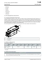
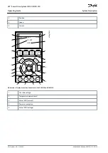
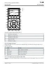
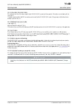
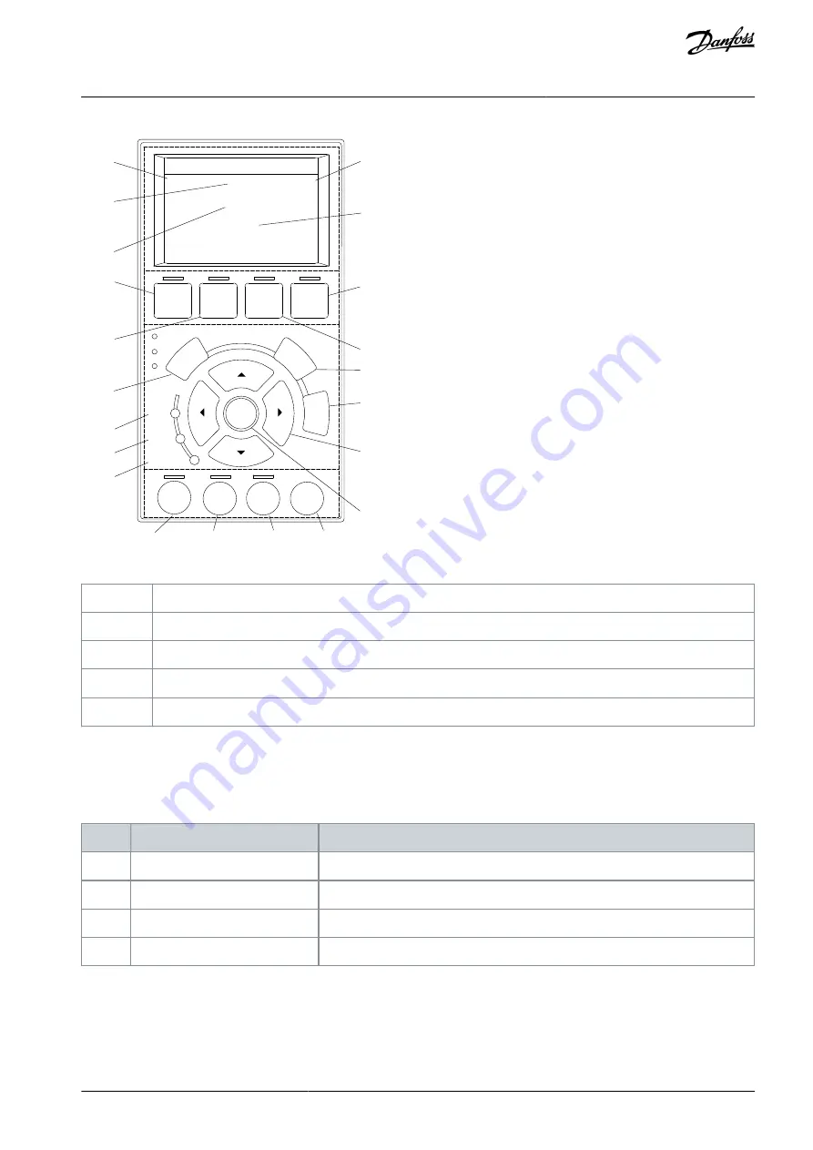
Illustration 10: Display Area when Connected to the ACM 510
1
Temperature power board
2
Temperature capacitor bank 1
3
Temperature capacitor bank 2
4
U
AUX
line voltage
5
Actual UDC (voltage)
3.8.2.2 B: Display menu keys
Menu keys are used for menu access for parameter set-up, toggling through status display modes during normal operation, and
viewing fault log data.
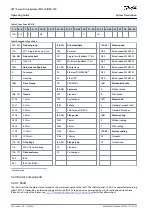
Table 11: Display Menu Keys
Key
Function
6
Status
Shows operational information.
7
Quick Menu
Allows access to parameters.
8
Main Menu
Allows access to parameters.
9
Alarm Log
Shows the last 10 alarms.
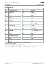
3.8.2.3 C: Navigation keys and indicator lights (LEDs)
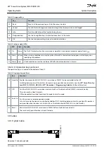
Navigation keys are used for moving the display cursor and provide operation control in local operation. There are also 3 status LEDs
in this area.
AQ262449648484en-000101 / 175R1135 | 39
Danfoss A/S © 2020.08
System Description
VLT® Servo Drive System ISD 510/DSD 510
Operating Guide


