-
16.
-
•
-
-
-
-
-
•
•
-
-
-
-
-
-
•
•
e3
0b
i2
64
.1
0
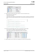
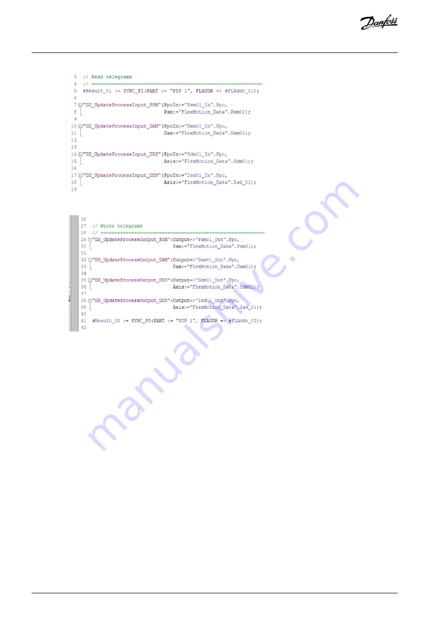
In operation block
Synchronous Cycle [OB61]
, enter the telegram write instructions as per the example below.
e3
0b
i2
65
.1
0
6.16 Programming Guidelines for TIA
Recommendations for implementation:
Only assign the
HwIdSubmodule
variable in the appropriate structure of each device present at the beginning of the program.
Use the constant that is created automatically by TIA in menu [PLC tags
→
Show all tags
→
System Constants], for example,
danfoss-isd-01~Device_object_1~Module_access_point
. Only assign this variable in the 1st PLC cycle for initialization. The struc-
tures to be used for each type of device are:
ISD 510:
AXIS_REF_DDS
DSD 510:
AXIS_REF_DDS
PSM 510:
PSM_REF
DAM 510:
DAM_REF
ACM 510:
ACM_REF
Initialize parameters that usually do not change only once at the beginning of the program.
Call the appropriate functions for each device present in every PLC cycle:
ISD 510:
DD_UpdateProcessInput_DDS
and
DD_UpdateProcessOutput_DDS
DSD 510:
DD_UpdateProcessInput_DDS
and
DD_UpdateProcessOutput_DDS
SDM 511/SDM 512:
DD_UpdateProcessInput_DDS
and
DD_UpdateProcessOutput_DDS
PSM 510:
DD_UpdateProcessInput_PSM
and
DD_UpdateProcessOutput_PSM
DAM 510:
DD_UpdateProcessInput_DAM
and
DD_UpdateProcessOutput_DAM
ACM 510:
DD_UpdateProcessInput_ACM
and
DD_UpdateProcessOutput_ACM
Only create instructions and other program parts between calling up function blocks
DD_UpdateProcessInput_xxx
and
DD_Up-
dateProcessOutput_xxx
.
Call up function blocks that provide status or error information with
Enable input
at the beginning of the program.
AQ262449648484en-000101 / 175R1135
130 | Danfoss A/S © 2020.08
Commissioning
VLT® Servo Drive System ISD 510/DSD 510
Operating Guide

