


Table 10: EMC Emission Test Results, H13–H14
RFI filter type
Conduct emission. Maximum shielded cable length [m
(ft)]
Radiated emission
EN 55011
Class B Housing,
trades and light
industries
Class A Group 1
Industrial envi-
ronment
Class A Group 2
Industrial envi-
ronment
Class B Hous-
ing, trades
and light in-
dustries
Class A Group
1 Industrial
environment
Class A Group
2 Industrial
environment
EN/IEC
61800-3
Category C1
First environ-
ment home and
office
Category C2
First environ-
ment home and
office
Category C3
Second environ-
ment industrial
Category C1
First environ-
ment home
and office
Category C2
First environ-
ment home
and office
Category C3
First environ-
ment home
and office
H2 RFI filter (EN 55011 A2, EN/IEC 61800-3 C3)
110–315 kW
(150– 450 hp)
3x380–480 V
IP20
No
No
150 m (492 ft)
No
No
Yes
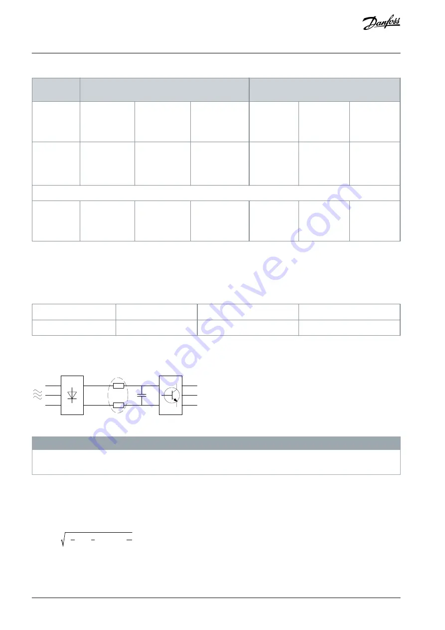
3.4.4 Harmonics Emission
A drive takes up a non-sinusoidal current from mains, which increases the input current I
RMS
. A non-sinusoidal current is trans-
formed with a Fourier analysis and split into sine-wave currents with different frequencies, that is, different harmonic currents I
n
with 50 Hz basic frequency:
Table 11: Harmonic Currents
I
1
I
5
I
7
Hz
50
250
350
The harmonics do not affect the power consumption directly, but increase the heat losses in the installation (transformer, cables).
So, in plants with a high percentage of rectifier load, maintain harmonic currents at a low level to avoid overload of the transformer
and high temperature in the cables.
e
7
5
h
a
0
3
4
.1
0
Illustration 23: DC-link Coils
N O T I C E
Some of the harmonic currents might disturb communication equipment connected to the same transformer or cause resonance
with power factor correction batteries.
To ensure low harmonic currents, the drive is equipped with DC-link coils as standard. This normally reduces the input current I
RMS
by 40%.
The voltage distortion on the mains supply voltage depends on the size of the harmonic currents multiplied by the mains impe-
dance for the frequency in question. The total voltage distortion THDv is calculated based on the individual voltage harmonics us-
ing this formula:
THD % =
U
2
5
+
U
2
7
+
...
+
U
2
N
(U
N
% of U)
3.4.4.1 Harmonics Emission Requirements
Equipment is connected to the public supply network.
AJ363928382091en-000101 / 130R0983
34 | Danfoss A/S © 2021.04
Product Overview
VLT® Flow Drive FC 111
Design Guide