


1
2
z
z
z
L1
L2
L3
PE
U
V
W
C
S
I
2
I
1
I
3
I
4
C
S
C
S
C
S
C
S
I
4
C
S
z
PE
3
4
5
6
e
7
5
za
0
6
2
.1
2
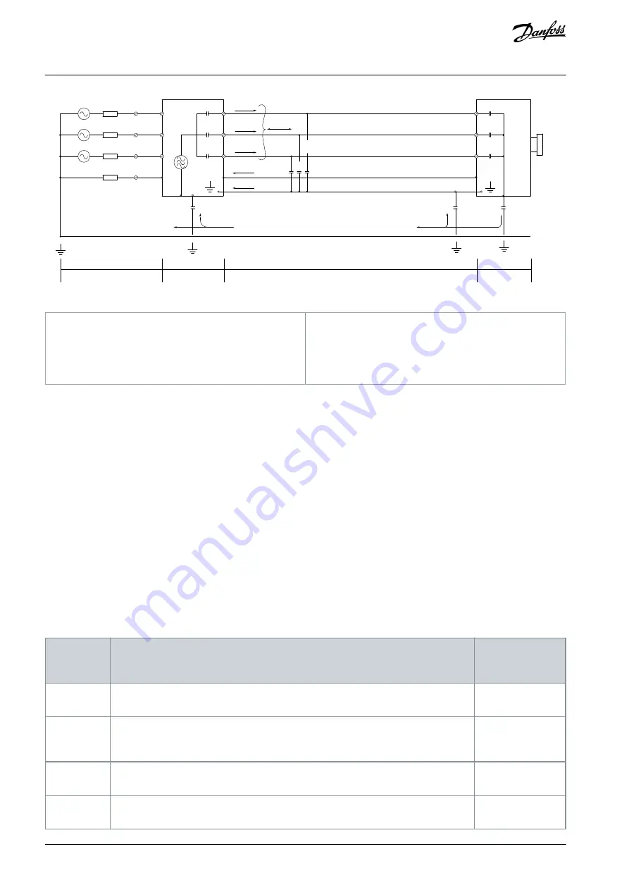
Illustration 22: Generation of Leakage Currents
1
Ground wire
2
Shield
3
AC mains supply
4
Drive
5
Shielded motor cable
6
Motor
The shield reduces the radiated interference, but increases the low-frequency interference on the mains. Connect the motor cable
shield to the drive enclosure and on the motor enclosure. This is best done by using integrated shield clamps to avoid twisted shield
ends (pigtails). Pigtails increase the shield impedance at higher frequencies, which reduces the shield effect and increases the leak-
age current (I
4
).
If a shielded cable is used for relay, control cable, signal interface, and brake, mount the shield on the enclosure at both ends. In
some situations, however, it is necessary to break the shield to avoid current loops.
If the shield is to be placed on a mounting plate for the drive, the mounting plate must be made of metal, to convey the shield
currents back to the unit. Moreover, ensure good electrical contact from the mounting plate through the mounting screws to the
drive chassis.
When using unshielded cables, some emission requirements are not complied with, although most immunity requirements are ob-
served.
To reduce the interference level from the entire system (unit+installation), make motor and brake cables as short as possible. Avoid
placing cables with a sensitive signal level alongside motor and brake cables. Radio interference higher than 50 MHz (airborne) is
especially generated by the control electronics.
3.4.2 Emission Requirements
The EMC product standard for drives defines 4 categories (C1, C2, C3, and C4) with specified requirements for emission and immuni-
ty. The following table states the definition of the 4 categories and the equivalent classification from EN 55011.
Table 7: Correlation between IEC 61800-3 and EN 55011
EN/IEC
61800-3 Cat-
egory
Definition
Equivalent emis-
sion class in EN
55011
C1
Drives installed in the first environment (home and office) with a supply voltage less than
1000 V.
Class B
C2
Drives installed in the first environment (home and office) with a supply voltage less than
1000 V, which are neither plug-in nor movable and are intended to be installed and com-
missioned by a professional.
Class A Group 1
C3
Drives installed in the second environment (industrial) with a supply voltage lower than
1000 V.
Class A Group 2
C4
Drives installed in the second environment with a supply voltage equal to or above 1000
V or rated current equal to or above 400 A or intended for use in complex systems.
No limit line. Make
an EMC plan.
AJ363928382091en-000101 / 130R0983
32 | Danfoss A/S © 2021.04
Product Overview
VLT® Flow Drive FC 111
Design Guide