


VLT
®
FCD Series
Installation
■
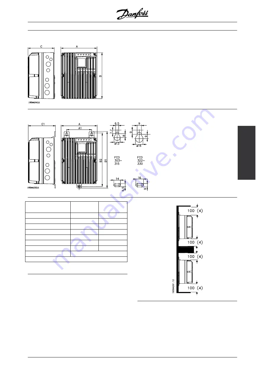
Mechanical dimensions, FCD, motor mounting
■
Mechanical dimensions, stand alone mounting
Mechanical dimensions in
mm
FCD 303-315
FCD 322-335
A
192
258
A1
133
170
B
244
300
B1
300
367
B2
284
346
C
142
151
C1
145
154
Cable Gland sizes
M16, M20, M25 x 1.5 mm
Space for cable inlets and service switch handle 100-150 mm
■
Spacing for mechanical installation
All units require a minimum of 100 mm air from other
components above and below the enclosure.
MG.04.B7.02 - VLT is a registered Danfoss trademark
7