


+
_
+
_
130BA053.11
Ref.
Config. mode
P 1-00
P 7-20 Process feedback
1 source
P 7-22 Process feedback
2 source
Process
PID
P 4-11 Motor speed
low limit [RPM]
P 4-12 Motor speed
low limit [Hz]
P 4-14 Motor speed
high limit [Hz]
P 4-13 Motor speed
high limit [RPM]
Low
High
Ramp
P 3-**
+f max.
P 4-19
Max. output
freq.
Motor
controller
-f max.
Speed
PID
P 7-0*
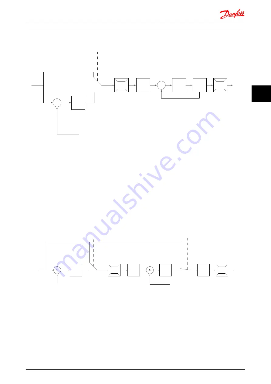
Illustration 4.16 Control Structure in Flux Sensorless
In the configuration shown,
1-01 Motor Control Principle
is
set to
[2] Flux sensorless
and
1-00 Configuration Mode
is set
to
[0] Speed open loop
. The resulting reference from the
reference handling system is fed through the ramp and
speed limitations as determined by the parameter settings
indicated.
An estimated speed feedback is generated to the Speed
PID to control the output frequency.
The Speed PID must be set with its P,I, and D parameters
(parameter group 7-0*).
Select
[3] Process
in
1-00 Configuration Mode
to use the
process PID control for closed loop control of speed or
pressure in the controlled application. The Process PID
parameters are found in parameter group 7-2* and 7-3*.
4.5.3 Control Structure in Flux with Motor Feedback
130BA054.11
P 3-**
P 7-0*
P 7-2*
+
_
+
_
P 7-20 Process feedback
1 source
P 7-22 Process feedback
2 source
P 4-11 Motor speed
low limit (RPM)
P 4-12 Motor speed
low limit (Hz)
P 4-13 Motor speed
high limit (RPM)
P 4-14 Motor speed
high limit (Hz)
High
Low
Ref.
Process
PID
Speed
PID
Ramp
P 7-00
PID source
Motor
controller
-f max.
+f max.
P 4-19
Max. output
freq.
P 1-00
Config. mode
P 1-00
Config. mode
Torque
Illustration 4.17 Control Structure in Flux with Motor Feedback
In the configuration shown,
1-01 Motor Control Principle
is
set to
[3] Flux w motor feedb
and
1-00 Configuration Mode
is set to
[1] Speed closed loop
.
The motor control in this configuration relies on a
feedback signal from an encoder mounted directly on the
motor (set in
1-02 Flux Motor Feedback Source
).
Select
[1] Speed closed loop
in
1-00 Configuration Mode
to
use the resulting reference as an input for the Speed PID
control. The Speed PID control parameters are located in
parameter group 7-0*.
Select
[2] Torque
in
1-00 Configuration Mode
to use the
resulting reference directly as a torque reference. Torque
Application Examples
VLT
®
Decentral Drive FCD 302
MG04H102 - VLT
®
is a registered Danfoss trademark
63
4
4