
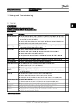

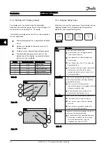


4.1.2 Setting LCP Display Values
The display area is activated when the adjustable
frequency drive receives power from AC line voltage, a DC
bus terminal, or an external 24 V DC supply.
The information displayed on the LCP can be customized
for user application.
•
Each display readout has a parameter associated
with it
•
Options are selected in the quick menu
Q3-13
Display Settings
•
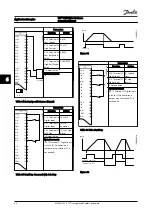
Display 2 has an alternate larger display option
•
The adjustable frequency drive status at the
bottom line of the display is generated automat-
ically and is not selectable
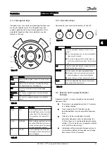
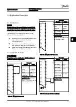
Display
Parameter number
Default setting
1.1
0-20
Motor RPMs
1.2
0-21
Motor current
1.3
0-22
Motor power (kW)
2
0-23
Motor frequency
3
0-24
Reference in percent
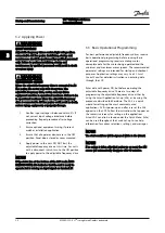
Table 4.1
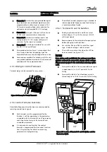
1.1
2
3
1.3
1.2
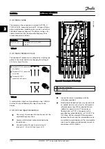
130BP041.10
799 RPM
Auto Remote Ramping
1 (1)
36.4 kW
7.83 A
0.000
53.2%
Status
Figure 4.2
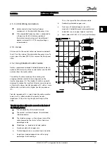
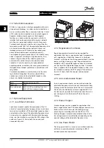
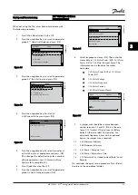
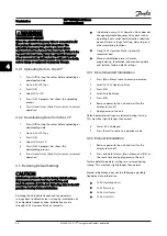
1.1
1.2
2
1.3
130BP062.10
207RPM
Auto Remote Running
1 (1)
24.4 kW
5.25A
6.9Hz
Status
Figure 4.3
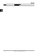
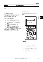
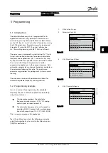
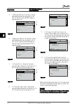
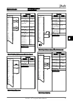
4.1.3 Display Menu Keys
Menu keys are used for menu access for parameter set-up,
toggling through status display modes during normal
operation, and viewing fault log data.
130BP045.10
Status
Quick
Menu
Main
Menu
Alarm
Log
Figure 4.4
Key
Function
Status
Shows operational information.
•
In auto mode, press to toggle between
status readout displays.
•
Press repeatedly to scroll through each
status display.
•
Press [Status] plus [
▲
] or [
▼
] to adjust the
display brightness.
•
The symbol in the upper right corner of the
display shows the direction of motor
rotation and which set-up is active. This is
not programmable.
Quick Menu
Allows access to programming parameters for
initial set-up instructions and many detailed
application instructions.
•
Press to access
Q2 Quick Setup
for
sequenced instructions to program the basic
frequency controller setup
•
Follow the sequence of parameters as
presented for the function set-up
Main Menu
Allows access to all programming parameters.
•
Press twice to access top-level index
•
Press once to return to the last location
accessed.
•
Press to enter a parameter number for
direct access to that parameter.
Alarm Log
Displays a list of current warnings, the last 10
alarms, and the maintenance log.
•
For details about the adjustable frequency
drive before it entered the alarm mode,
select the alarm number using the
navigation keys and press [OK].
Table 4.2
User Interface
VLT
®
HVAC Drive D-Frame
Instruction Manual
4-2
MG16D222 - VLT
®
is a registered Danfoss trademark
4
4


