


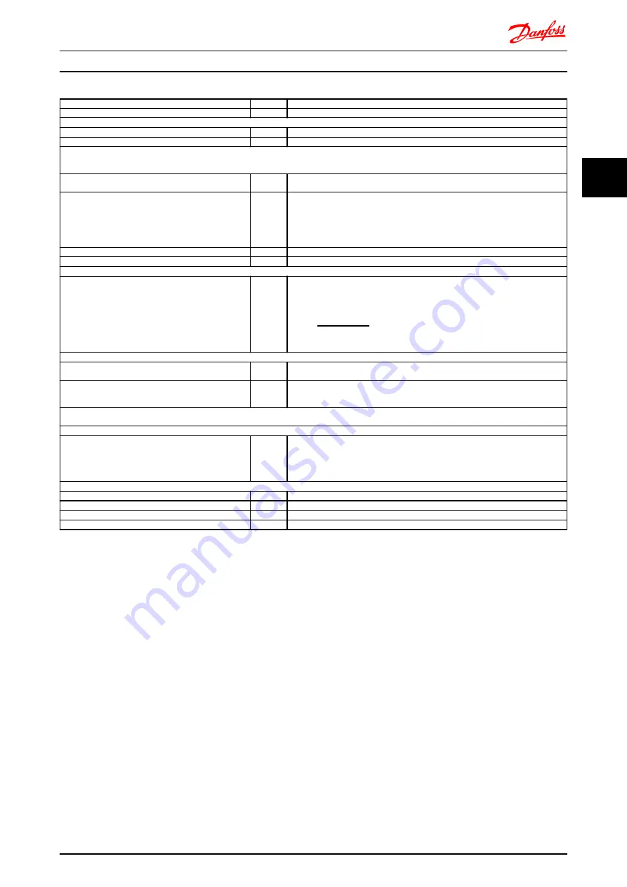
Function
Par. no.
Setting
Initialize the frequency converter
14-22
[2] Initialization - make a power cycling - press reset
1) Set motor parameters:
Set the motor parameters according to name plate data
1-2*
As stated on motor name plate
Perform a full Automation Motor Adaptation
1-29
[1] Enable complete AMA
2) Check that motor is running in the right direction.
When motor is connected to frequency converter with straight forward phase order as U - U; V- V; W - W motor shaft usually turns clockwise seen into shaft
end.
Press “Hand On” LCP key. Check shaft direction by
applying a manual reference.
If motor turns opposite of required direction:
1. Change motor direction in
4-10 Motor Speed Direction
2. Turn off mains - wait for DC link to discharge - switch
two of the motor phases
4-10
Select correct motor shaft direction
Set configuration mode
1-00
[3] Process
Set Local Mode Configuration
1-05
[0] Speed Open Loop
3) Set reference configuration, ie. the range for reference handling. Set scaling of analog input in par. 6-xx
Set reference/feedback units
Set min. reference (10
°
C)
Set max. reference (80
°
C)
If set value is determined from a preset value (array
parameter), set other reference sources to No Function
3-01
3-02
3-03
3-10
[60]
°
C Unit shown on display
-5
°
C
35
°
C
[0] 35%
Ref
=
Par
. 3 − 10(0)
100
× ((
Par
. 3 − 03) − (
par
. 3 − 02)) = 24, 5°
C
3-14 Preset Relative Reference
to
3-18 Relative Scaling Reference Resource
[0] = No
Function
4) Adjust limits for the frequency converter:
Set ramp times to an appropriate value as 20 sec.
3-41
3-42
20 sec.
20 sec.
Set min. speed limits
Set motor speed max. limit
Set max. output frequency
4-11
4-13
4-19
300 RPM
1500 RPM
60 Hz
Set S201 or S202 to wanted analog input function (Voltage (V) or milli-Amps (I))
NOTE! Switches are sensitive - Make a power cycling keeping default setting of V
5) Scale analog inputs used for reference and feedback
Set terminal 53 low voltage
Set terminal 53 high voltage
Set terminal 54 low feedback value
Set terminal 54 high feedback value
Set feedback source
6-10
6-11
6-24
6-25
7-20
0V
10V
-5
°
C
35
°
C
[2] Analog input 54
6) Basic PID settings
Process PID Normal/Inverse
7-30
[0] Normal
Process PID Anti Wind-up
7-31
[1] On
Process PID start speed
7-32
300 rpm
Save parameters to LCP
0-50
[1] All to LCP
Table 3.3 Example of Process PID Control set-up
Optimisation of the process regulator
The basic settings have now been made; all that needs to
be done is to optimise the proportional gain, the
integration time and the differentiation time (
7-33 Process
PID Proportional Gain
,
7-34 Process PID Integral Time
,
7-35 Process PID Differentiation Time
). In most processes,
this can be done by following the guidelines given below.
1.
Start the motor
2.
Set
7-33 Process PID Proportional Gain
to 0.3 and
increase it until the feedback signal again begins
to vary continuously. Then reduce the value until
the feedback signal has stabilised. Now lower the
proportional gain by 40-60%.
3.
Set
7-34 Process PID Integral Time
to 20 sec. and
reduce the value until the feedback signal again
begins to vary continuously. Increase the
integration time until the feedback signal
stabilises, followed by an increase of 15-50%.
4.
Only use
7-35 Process PID Differentiation Time
for
very fast-acting systems only (differentiation
time). The typical value is four times the set
integration time. The differentiator should only be
used when the setting of the proportional gain
and the integration time has been fully
optimised. Make sure that oscillations on the
feedback signal is sufficiently dampened by the
lowpass filter on the feedback signal.
If necessary, start/stop can be activated a number of times
in order to provoke a variation of the feedback signal.
3.4.5 Ziegler Nichols Tuning Method
In order to tune the PID controls of the frequency
converter, several tuning methods can be used. One
approach is to use a technique which was developed in
Introduction to FC 300
FC 300 Design Guide
MG.33.BD.02 - VLT
®
is a registered Danfoss trademark
35
3
3