


8.12 Final Setup and Test
To test the set-up and ensure that the frequency converter
is running, follow these steps.
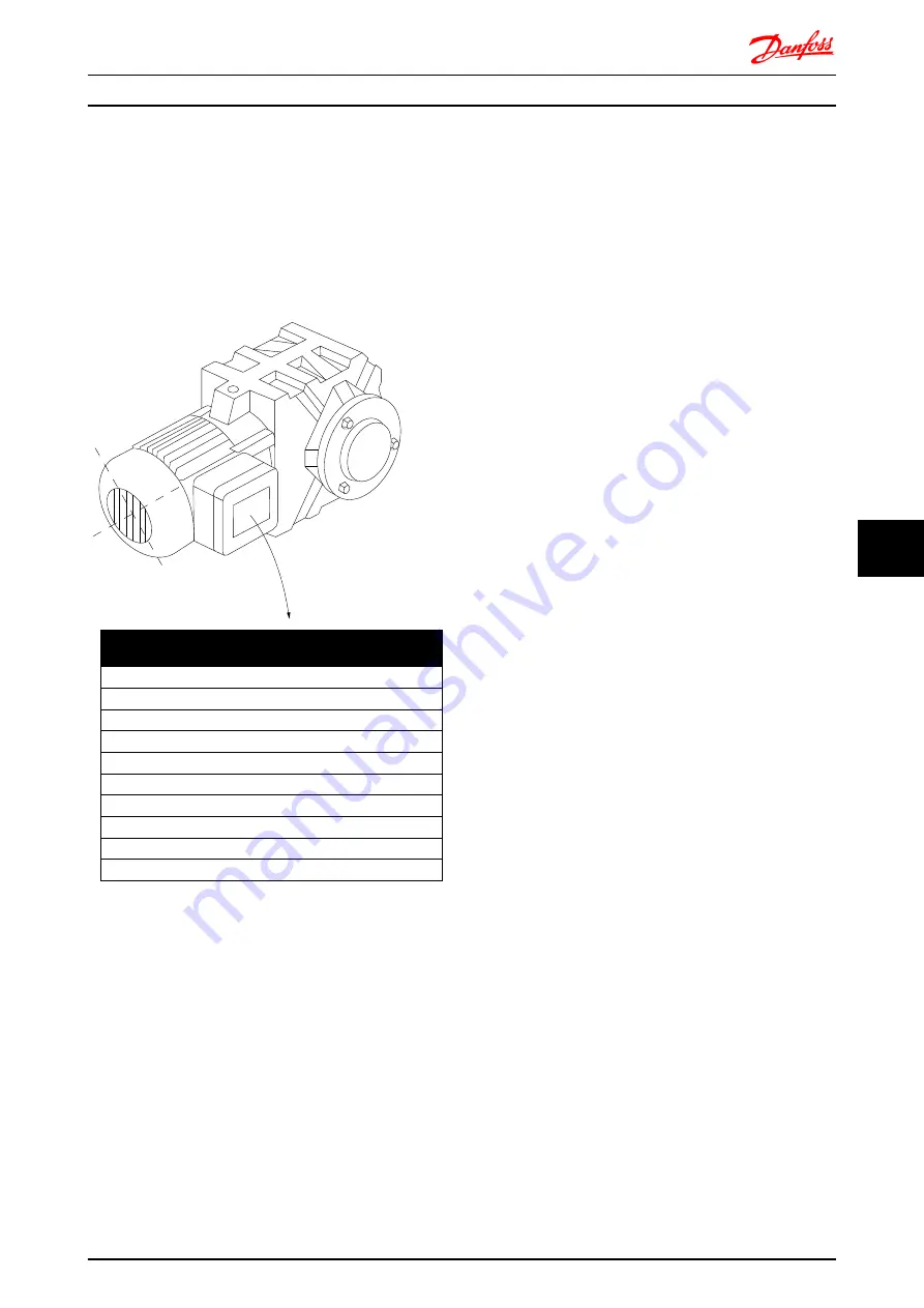
Step 1. Locate the motor name plate
The motor is either star- (Y) or delta- connected (Δ). This
information is located on the motor name plate data.
3~ MOTOR NR. 1827421 2003
S/E005A9
1,5
KW
n2 31,5
/min.
400
Y
V
n1 1400
/min.
50
Hz
COS
0,80
3,6
A
1,7L
B
IP 65
H1/1A
BAUER D-7 3734 ESLINGEN
130B
T307.10
Step 2. Enter the motor name plate data in this parameter
list.
To access this list first press the [QUICK MENU] key then
select “Q2 Quick Setup”.
1.
1-20 Motor Power [kW]
1-21 Motor Power [HP]
2.
1-22 Motor Voltage
3.
1-23 Motor Frequency
4.
1-24 Motor Current
5.
1-25 Motor Nominal Speed
Step 3. Activate the Automatic Motor Adaptation (AMA)
Performing an AMA will ensure optimum performance.
The AMA measures the values from the motor model
equivalent diagram.
1.
Connect terminal 37 to terminal 12 (if terminal 37
is available).
2.
Connect terminal 27 to terminal 12 or set
5-12 Terminal 27 Digital Input
to 'No function'.
3.
Activate the AMA
1-29 Automatic Motor
Adaptation (AMA)
.
4.
Choose between complete or reduced AMA. If a
Sine-wave filter is mounted, run only the reduced
AMA, or remove the Sine-wave filter during the
AMA procedure.
5.
Press the [OK] key. The display shows “Press
[Hand on] to start”.
6.
Press the [Hand on] key. A progress bar indicates
if the AMA is in progress.
Stop the AMA during operation
1.
Press the [OFF] key - the frequency converter
enters into alarm mode and the display shows
that the AMA was terminated by the user.
Successful AMA
1.
The display shows “Press [OK] to finish AMA”.
2.
Press the [OK] key to exit the AMA state.
Unsuccessful AMA
1.
The frequency converter enters into alarm mode.
A description of the alarm can be found in the
Warnings and Alarms
chapter.
2.
"Report Value” in the [Alarm Log] shows the last
measuring sequence carried out by the AMA,
before the frequency converter entered alarm
mode. This number along with the description of
the alarm will assist you in troubleshooting. If you
contact Danfoss for service, make sure to mention
number and alarm description.
Unsuccessful AMA is often caused by incorrectly registered
motor name plate data or a too big difference between
the motor power size and the frequency converter power
size.
Step 4. Set speed limit and ramp times
Set up the desired limits for speed and ramp time:
3-02 Minimum Reference
3-03 Maximum Reference
4-11 Motor Speed Low Limit [RPM]
or
4-12 Motor
Speed Low Limit [Hz]
4-13 Motor Speed High Limit [RPM]
or
4-14 Motor
Speed High Limit [Hz]
3-41 Ramp 1 Ramp up Time
3-42 Ramp 1 Ramp Down Time
Electrical Installation
FC 300 Design Guide
MG.33.BD.02 - VLT
®
is a registered Danfoss trademark
227
8
8