


Go to position 2 to get a pallet:
1.
Switch off digital input 19 and switch on digital
input 27 to select position 2.
2.
Swith on digital 18 to move to position 2.
3.
Wait until digital out 42 is turned on, which
means the target position is reached. Make sure
the pallet transfer starts after the position is
reached. Otherwise, adjust the system or
parameters.
4.
Switch off digital input 18 to stop positioning.
5.
Wait until the pallet is transferred to the cart.
Go to position 3 to deliver the pallet:
1.
Switch off digital input 19 and switch on digital
input 27 to select position 3.
2.
Swith on digital 18 to move to position 3.
3.
Wait until digital out 42 is turned on, which
means the target position is reached. Make sure
the pallet transfer starts after the position is
reached. Otherwise, adjust the system or
parameters.
4.
Switch off digital input 18 to stop positioning.
5.
Wait until the pallet is transferred to the cart.
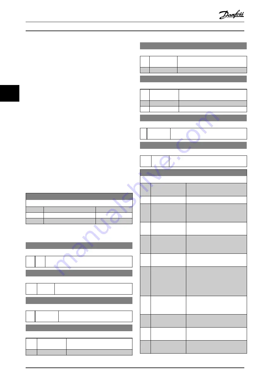
4.7 Parameters for Positioning Control
37-00 Application Mode
Option:
Function:
[0]
*
Drive mode
[1]
Center winder
[2]
Position control
4.7.1 Digital Input and Output Settings
5-10 Terminal 18 Digital Input
Option:
Function:
[8]
*
Start Functions are described in parameter group
5-1*
Digital Inputs
.
5-11 Terminal 19 Digital Input
Option:
Function:
[10]
*
Reversing Functions are described in parameter group
5-1* Digital Inputs
.
5-12 Terminal 27 Digital Input
Option:
Function:
[2]
*
Coast inverse Functions are described in parameter group
5-1* Digital Inputs
.
5-13 Terminal 29 Digital Input
Option:
Function:
[14]
*
Jog
Functions are described in parameter
group
5-1* Digital Inputs
.
[32]
Pulse time based
5-14 Terminal 32 Digital Input
Option:
Function:
[0]
*
No operation
Functions are described in parameter
group
5-1* Digital Inputs
.
[82] Encoder input B
5-15 Terminal 33 Digital Input
Option:
Function:
[0]
*
No operation
Functions are described in parameter
group
5-1* Digital Inputs
.
[32] Pulse time based
[81] Enocder input A
5-16 Terminal 31 Digital Input
Option:
Function:
[0] No operation Functions are described in parameter group
5-1* Digital Inputs
.
5-11 Terminal 19 Digital Input
Option:
Function:
[10]
*
Reversing Functions are described in parameter group
5-1* Digital Inputs
.
5-40 Function Relay
Option:
Function:
[0]
No operation
Default setting for all digital and
relay outputs.
[1]
Control Ready
The control card is ready.
[2]
Drive ready
The frequency converter is ready to
operate. Mains and control supplies
are OK.
[3]
Drive rdy/rem ctrl
The frequency converter is ready for
operation, and is in
Auto On
mode.
[4]
Stand-by / no
warning
Ready for operation. No start or stop
commands have been applied. No
warnings are active.
[5]
Running
The motor is running and a shaft
torque is present.
[6]
Running / no
warning
The output speed is higher than the
speed set in
1-82 Min Speed for
Function at Stop [Hz]
. The motor is
running and no warnings are
present.
[7]
Run in range/no
warn
The motor is running within the
programmed current ranges set in
4-50 Warning Current Low
.
[8]
Run on ref/no warn
The motor runs at reference speed.
No warnings.
[9]
Alarm
An alarm activates the output. No
warnings.
[10]
Alarm or warning
An alarm or warning activates the
output.
Positioning Control
VLT
®
AutomationDrive FC 360
20
Danfoss A/S © 11/2014 All rights reserved.
MG06E102
4
4