


NOTICE!
Use line cables of equal length (
±
10%) and the same wire size for all three phases on both rectifier sections.
Shielding of Cables
Avoid installation with twisted shield ends (pigtails). They spoil the shielding effect at higher frequencies. If it is necessary to
break the shield to install a motor isolator or motor contactor, the shield must be continued at the lowest possible HF
impedance.
Connect the motor cable shield to both the decoupling plate of the adjustable frequency drive and the metal housing of
the motor.
Make the shield connections with the largest possible surface area (cable clamp) by using the supplied installation devices
within the adjustable frequency drive.
Cable Length and Cross-Section
Keep the motor cable as short as possible to reduce the noise level and leakage currents.
Switching Frequency
When adjustable frequency drives are used together with sine-wave filters to reduce the acoustic noise from a motor, set
the switching frequency according to the instructions in
14-01 Switching Frequency
.
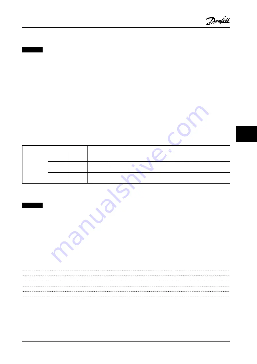
Term. no.
96
97
98
99
U
V
W
PE
1)
Motor voltage 0–100% of AC line voltage.
3 wires out of motor
U1
V1
W1
PE
1)
Delta-connected
W2
U2
V2
6 wires out of motor
U1
V1
W1
PE
1)
Star-connected U2, V2, W2
U2, V2, and W2 to be interconnected separately.
Table 7.25 Terminals
1)
Protective Ground Connection
NOTICE!
In motors without phase insulation paper or other insulation reinforcement suitable for operation with voltage supply,
fit a sine-wave filter on the output of the adjustable frequency drive.
7.1.4 12-Pulse Transformer Selection Guidelines
Transformers used in conjunction with 12-pulse adjustable frequency drives must conform to the following specifications.
Loading is based on 12-pulse K-4 rated transformer with 0.5% voltage and impedance balance between secondary windings.
Leads from the transformer to the input terminals on the adjustable frequency drive are required to be equal length within
10%.
Connection
Dy11 d0 or Dyn 11d0
Phase shift between secondaries
30°
Voltage difference between secondaries
<0.5%
Short-circuit impedance of secondaries
>5%
Short-circuit impedance difference between secondaries
<5% of short-circuit impedance
Other
No grounding of the secondaries allowed. Static shield recommended
Electrical Installation
Design Guide
MG34S222
Danfoss A/S © Rev. 2014-02-10 All rights reserved.
207
7
7
Summary of Contents for VLT AutomationDrive FC 300
Page 2: ......