


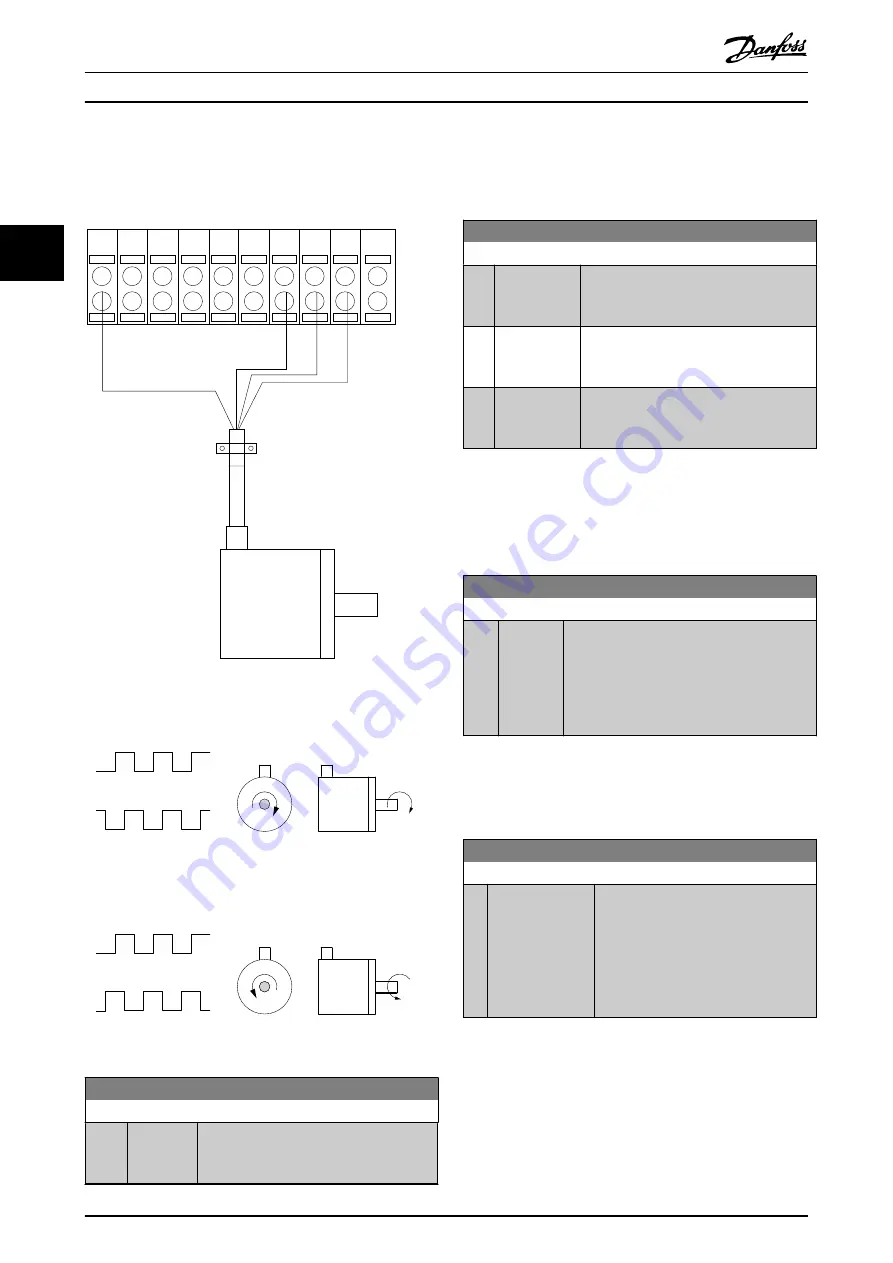
Encoder Connection to the frequency converter
24 V incremental encoder. Max. cable length 5 m.
130BA090.11
+24V DC
A
B
GND
13
12
18
37
32
27
19
29
33
20
24V or 10-30V encoder
Illustration 3.39
B
A
B
A
130BA646.10
CW
CCW
Illustration 3.40
5-70 Term 32/33 Pulses per Revolution
Range:
Function:
1024
*
[1 - 4096 ] Set the encoder pulses per revolution on
the motor shaft. Read the correct value
from the encoder.
NOTE
This parameter cannot be adjusted while the motor is
running.
5-71 Term 32/33 Encoder Direction
Option:
Function:
Change the detected encoder rotation
direction without changing the wiring to
the encoder.
[0]
*
Clockwise
Sets channel A 90° (electrical degrees)
behind channel B upon clockwise rotation
of the encoder shaft.
[1]
Counter
clockwise
Sets channel A 90° (electrical degrees)
ahead of channel B upon clockwise
rotation of the encoder shaft.
NOTE
This parameter cannot be adjusted while the motor is
running.
3.7.8 5-8* I/O Options
5-80 AHF Cap Reconnect Delay
Range:
Function:
25 s
*
[1 - 120
s]
Guarantees a minimum off-time for the
capacitors. The timer starts once the AHF
capacitor disconnects and needs to expire
before the output is allowed to be on again. It
will only turn on again if the drive power is
between 20% and 30%.
3.7.9 5-9* Bus Controlled
This parameter group selects digital and relay outputs via
a fieldbus setting.
5-90 Digital & Relay Bus Control
Range:
Function:
0
*
[0 - 2147483647 ] This parameter holds the state of the
digital outputs and relays that is
controlled by bus.
A logical '1' indicates that the output is
high or active.
A logical '0' indicates that the output is
low or inactive.
Parameter Descriptions
VLT
®
AutomationDrive Programmming Guide
88
MG33ME02 - VLT
®
is a registered Danfoss trademark
3
3