


•
•
•
•
•
•
e3
0b
d8
88
.1
0
CONVERTER SUPPLY
VALID FOR 380 - 415V FWP 50Hz
3 ~ Motor
MIN. SWITCHING FREQ. FOR PWM CONV. 3kHz
l = 1.5XI
M,N
t
OL
= 10s
t
COOL
= 10min
MIN. FREQ. 5Hz
MAX. FREQ. 85 Hz
PWM-CONTROL
f [Hz]
Ix/I
M,N
PTC
°C
DIN 44081/-82
Manufacture xx EN 60079-0
EN 60079-7
СЄ
1180
Ex-e ll T3
5
15
25
50
85
0.4
0.8
1.0
1.0
0.95
1
xЗ
2
3
4
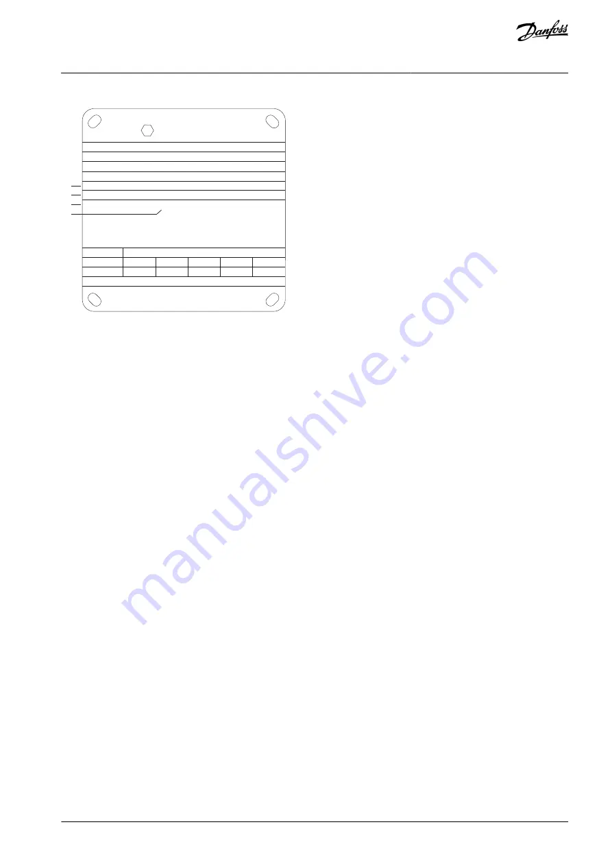
Illustration 32: Motor Nameplate showing Drive Requirements
When matching drive and motor, Danfoss specifies the following extra requirements to ensure adequate motor thermal protection:
Do not exceed the maximum allowed ratio between drive size and motor size. The typical value is I
VLT,n
≤ 2 x I
m,n
.
Consider all voltage drops from drive to motor. If the motor runs with lower voltage than listed in the U/f characteristics, current
can increase, triggering an alarm.
6.2.4 Mains Dropout
During a mains dropout, the drive keeps running until the DC-link voltage drops below the minimum stop level. The minimum stop
level is typically 15% below the lowest rated supply voltage. The mains voltage before the dropout and the motor load determines
how long it takes for the drive to coast.
Configure the mains dropout function of the drive in
parameter 14-10 Mains Failure
. The options are:
Trip lock.
Coast with flying start.
Kinetic back-up.
Controlled ramp-down.
Flying start
Flying start enables catching a motor that is spinning freely due to a mains dropout. This option is relevant for high-inertia applica-
tions, such as centrifuges and fans.
Kinetic back-up
This selection ensures that the drive runs as long as there is energy in the system. For short mains dropout, the operation is restored
after mains return without bringing the application to a stop or losing control at any time. Several variants of kinetic back-up can be
selected.
Configure the behavior of the drive at mains dropout in
parameter 14-10 Mains Failure
and
parameter 1-73 Flying Start
.
6.2.5 Built-in PID Controller
The 4 built-in proportional, integral, derivative (PID) controllers eliminate the need for auxiliary control devices.
One of the PID controllers maintains constant control of closed-loop systems where regulated flow, temperature, or other system
requirements must be maintained. The drive can provide selfreliant control of the motor speed in response to feedback signals from
remote sensors. The drive accommodates 2 feedback signals from 2 different devices. This feature allows regulating a system with
different feedback requirements. The drive makes control decisions by comparing the 2 signals to optimize system performance.
Use the 3 extra and independent controllers for controlling other process equipment, such as chemical feed pumps, valve control, or
for aeration with different levels.
6.2.6 Automatic Restart
The drive can be programmed to restart the motor automatically after a minor trip, such as momentary power loss or fluctuation.
AJ300847815559en-000101 / 130R0337 | 47
Danfoss A/S © 2020.09
Product Features
VLT® AQUA Drive FC 202
Design Guide