


VLT
®
6000 HVAC Series
Programming
116 DC brake cut-in frequency
(DC BRAKE CUT-IN)
Value:
0.0 (OFF) - par. 202
Output frequency high limit, f
MAX
✭
OFF
Function:
This parameter is used for setting the DC brake cut-in
frequency at which DC braking is to be activated
in connection with a stop command.
Description of choice:
Set the desired frequency.
117 Motor thermal protection
(MOT. THERM PROTEC)
Value:
No protection (NO PROTECTION)
[0]
Thermistor warning (THERMISTOR WARNING)
[1]
Thermistor trip (THERMISTOR FAULT)
[2]
ETR Warning 1 (ETR WARNING 1)
[3]
✭
ETR Trip 1 (ETR TRIP 1)
[4]
ETR Warning 2 (ETR WARNING 2)
[5]
ETR Trip 2 (ETR TRIP 2)
[6]
ETR Warning 3 (ETR WARNING 3)
[7]
ETR Trip 3 (ETR TRIP 3)
[8]
ETR Warning 4 (ETR WARNING 4)
[9]
ETR Trip 4 (ETR TRIP 4)
[10]
Function:
The frequency converter is able to monitor the motor
temperature in two different ways:
-
Via a thermistor sensor fitted to the motor. The
thermistor is connected to one of the analog
input terminals 53 and 54.
-
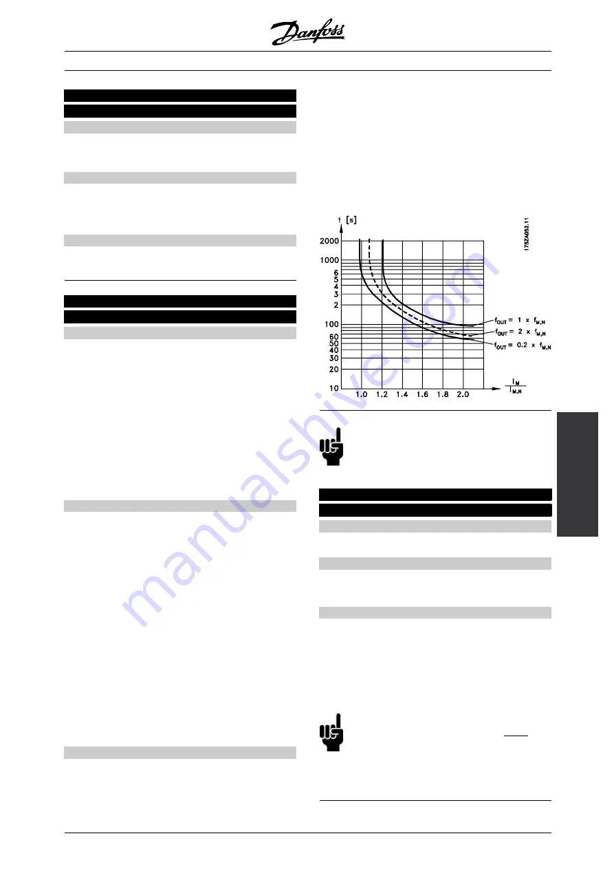
Calculation of the thermal load (ETR - Electronic
Thermal Relay), based on the current load and
the time. This is compared with the rated motor
current I
M,N
and the rated motor frequency f
M,N
.
The calculations made take into account the
need for a lower load at lower speeds because
of less cooling in the motor itself.
ETR functions 1-4 do not start calculating the load until
there is a switch-over to the Setup in which they were
selected. This enables the use of the ETR function,
even where two or several motors alternate.
Description of choice:
Select
No protection
[0] if no warning or tripping is
required when the motor is overloaded.
Select
Thermistor warning
[1] if a warning is desired
when the connected thermistor gets too hot.
Select
Thermistor trip
[2] if cutting out (trip) is desired
when the connected thermistor overheats.
Select
ETR Warning 1-4
, if a warning is to come
up on the display when the motor is overloaded
according to the calculations.
The frequency converter can also be programmed to
give off a warning signal via one of the digital outputs.
Select
ETR Trip 1-4
if tripping is desired when the
motor is overloaded according to the calculations.
NB!:
In UL / cUL applications ETR provides class
20 motor overload profection in accordance
with National Electrical Code.
118 Motor power factor (Cos
ϕ
)
(MOTOR PWR FACT)
Value:
0.50 - 0.99
✭
0.75
Function:
This parameter calibrates and optimizes the AEO
function for motors of different power factor (Cos
ϕ
).
Description of choice:
Motors having > 4 poles have a lower power factor
which would restrict or prevent use of the AEO function
for energy savings. This parameter allows the user
to calibrate the AEO function to the power factor of
the motor so that AEO can be used with motors of
6, 8, and 12 poles as well as 4 and 2 poles.
NB!:
The default value is 0.75 and should
NOT
be changed unless the specific motor
has power factor lower than 0.75. This
is typically the case for motors having more than
4 poles or low efficiency motors.
✭
= factory setting. () = display text [] = value for use in communication via serial communication port
MG.61.A5.02 - VLT is a registered Danfoss trademark
91