1
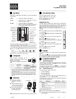
Fig 2
Fig 1
INITIAL START-UP
Slide the battery cover to the left to
reveal the batteries. Remove the
paper insulator from between the
batteries and contacts. The blank
display will change to actual room
temperature in large characters and
the required room temperature in
smaller characters. A typical display
where the actual room temperature
is 21°C and the required room
temperature is 20°C is shown as
Fig.1.
If the room temperature is lower than
the required temperature then a
small flame symbol will appear at the
top right hand side of the display
indicating that the thermostat has
switched on. (See Fig 2)
TEMPERATURE ADJUSTMENT
Use the
s
and
t
buttons to raise or lower the required
temperature.
SELECTING SETBACK MODE
To select setback mode, press both
s
and
t
buttons together. The display will
change to show actual temperature and
setback temperature. An "n" symbol is
also lit to signify that the thermostat is
now in setback mode. Fig 3 shows a typical display.
Use the
s
and
t
buttons to adjust the setback
temperature to the required value. This can be adjusted
between 30°C and 5°C. Please note that the thermostat
can also be set to "Off", should this be required.
Note:
This setback temperature value will be used every
time the thermostat is put into setback mode unless it is
altered at any time when the thermostat is in set-back
mode.
If the room temperature drops to below the selected
setback temperature, a flame symbol will light to indi-
cate that the thermostat has switched on.
CANCELLING THE SET-BACK MODE
The setback is cancelled manually at any time by press-
ing both
s
and
t
buttons together for a second time.
RT1-RF
Remote Electronic Room Thermostat with Set-Back Feature and Radio
Frequency Communication (Independently Surface Mounted)
USER INSTRUCTIONS
d
d
Fig 3
n
ESTABLISHING COMMUNICATION BETWEEN THE
RT1-RF THERMOSTAT AND ITS RX1 RECEIVER
MODULE
Once the programming has been completed,
communication between the thermostat and the receiver
module has to be established.
SINGLE ZONE SYSTEM WITH RX1 RECEIVER
1 - Press and hold the
t
and + buttons of the RT1-RF
for at least 3 seconds. The thermostat will now
transmit a continuous signal which contains its unique
identity for a period of 5 minutes.
2 - Within the 5 minute period go to the RX1 receiver
module and press both "PROG" and "CH1" buttons
together and hold for at least 3 seconds, then release.
During this process the RX1 receiver will have learnt
the unique transmission code of the thermostat and
will in future react to all transmissions from that
thermostat.
To stop the continuous transmission on the RT1-RF
unit press the
s
button.
TWO ZONE SYSTEM WITH RX2 RECEIVER
1 - Repeat as above for zone one (CH1).
2 - Repeat steps one and two above for zone two,
remembering to press "PROG" and "CH2" on the RX2
receiver.
THREE ZONE SYSTEM WITH RX3 RECEIVER
1 - Repeat as above for zones 1 and 2 (CH1 and CH2).
2 - Repeat as above for zone 3, remembering to press
"PROG" and "CH3" on the RX3 receiver.
BATTERY REPLACEMENT
When the batteries approach the end of their life a battery
symbol will flash on the left hand side of the display (See
Fig 4) When this symbol appears both batteries should
be replaced with high quality alkaline cells. Having
replaced the batteries the required temperature should
be re-set using the
s t
keys.
Fig 4


