Service Manual
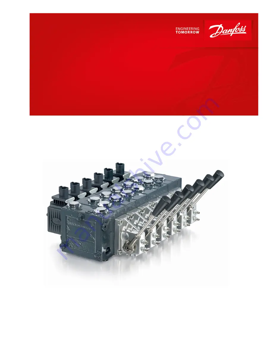
PVG 32
powersolutions.danfoss.com
Page 1: ...Service Manual PVG 32 powersolutions danfoss com ...
Page 2: ...hanged Rev February 2017 Updated with PVE Series 7 0301 May 2014 Converted to Danfoss layout DITA CMS BA Feb 2006 Aug 2013 Various changes AB BA Service Manual PVG 32 Proportional Valve Group 2 Danfoss February 2017 11039167 AX00000031en US0301 ...
Page 3: ...sponds in one direction only 16 Main valve spool moves without oil passing to cylinder motor 16 Cylinder motor operates without remote controller being operated 17 Cylinder motor responds slowly to remote electrical or hydraulic controller actuation 17 Erratic cylinder motor response to electrical or hydraulic controller operation 17 Hydraulic oil supply 18 Electrical supply 18 Hydraulic remote pi...
Page 4: ...8 Troubleshooting Considerations 38 PVEO ON OFF electrical actuator 39 PVPC plug for external pilot control 42 PVMR Friction Module 42 Service Manual PVG 32 Proportional Valve Group Contents 4 Danfoss February 2017 11039167 AX00000031en US0301 ...
Page 5: ...s Remove the unit Chock the wheels on the vehicle or lock the mechanism to inhibit movement Prior to performing repairs remove the unit from the vehicle machine Be aware that hydraulic fluid may be under high pressure and or hot Inspect the outside of the valve stack and fittings for damage Cap hoses after removal to prevent contamination Keep it clean Cleanliness is a primary means of assuring sa...
Page 6: ...ause burns Use caution when dealing with hydraulic fluid under pressure Relieve pressure in the system before removing hoses fittings gauges or components Never use your hand or any other body part to check for leaks in a pressurized line Seek medical attention immediately if you are cut by hydraulic fluid Personal safety W Warning Protect yourself from injury Use proper safety equipment including...
Page 7: ... activation PVH Cover for hydraulic activation PVMF Cover for mechanical float PVMR Cover for friction detent PVMR or float position PVEH PVES PVEA Electrical activation PVEM Electrical activation PVEO Electrical activation Service Manual PVG 32 Proportional Valve Group Introduction Danfoss February 2017 11039167 AX00000031en US0301 7 ...
Page 8: ...n against overload and or cavitation An adjustable Load Sensing LS pressure limiting valve 12 can be built into the A and B ports of pressure compensated basic modules to limit the pressure from the individual working functions The LS pressure limiting valves save energy compared to the shock valves PVLP With PVLP all the oil flow to the working function flows across the combined shock and suction...
Page 9: ...nection port A 16 LS connection port B 17 Suction valve PVLA 18 Load drop check valve 19 Pilot oil supply for PVE 20 Max oil flow adjustment screws for ports A and B PVP PVB PVB PVPC plug for external pilot oil supply PVPC with check valve for open center PVP PVPC with check valve is used in systems where it is necessary to operate the PVG 32 valve by means of the electrical remote control without...
Page 10: ... systems where it is necessary to supply the PVG 32 valve with oil from a manually operated emergency pump without directing oil flow to the pilot oil supply oil consumption about 1 l min 0 25 US gal min When the main pump is working normally the oil is directed through the PVPC plug through the pressure reduction valve to the electrical actuators When the main pump flow fails the external shuttle...
Page 11: ...t the necessity of holding the mechanical lever PVMR should only be used together with PVB basic modules with pressure compensator PVMF Mechanical float position lock This allows the float spool to be held in the float position after release of the mechanical handle PVMF P A F Standard assembly P B F Optional assembly Service Manual PVG 32 Proportional Valve Group Operation Danfoss February 2017 1...
Page 12: ...en the small dead band of the spools and the hysteresis of the PVEM actuator of 20 involves a risk of building up a LS pressure in neutral position PVBS main spools for pressure control In a few systems load sensing pump pressure may result in unstable adjustment of the oil flow and a tendency towards system hunting This may be the case with working functions that have a large moment of inertia or...
Page 13: ... pump side module in open center version the relief to tank of the LS signal means that the pressure in the system is reduced to the sum of the tank port pressure plus the neutral flow pressure for the pump side module For a PVP pump side module in closed center version relief to tank of the LS signal occurs when the pressure is reduced by the sum of the tank port pressure for the pump side module...
Page 14: ...lable ask him What type of fault it is and how it affects the system How long he has he felt that something has been wrong If he has fiddled with the components If he has any hydraulic and electrical diagrams available Diagrams are often found in the instructions included with vehicles machines Unfortunately they are often so technical that they are not of much use in a fault location situation Ho...
Page 15: ...ng main spool Remove manual electrical and hydraulic actuators from the valve section Remove main spool from valve section and inspected for damage If no damage reinstall the main valve spool and it should move freely in the valve section bore Replace the valve module and main spool If any damage is found on the main spool Check movement of manual lever when electrical controller is operated If ma...
Page 16: ...or replace remote hydraulic controller Main valve spool moves without oil passing to cylinder motor Cause Check Corrective action Insufficient oil supply to valve Check the pump per manufacturers procedure Repair or replace pump per manufacturers procedure Optional pressure compensator in valve section not functioning Check compensator spool Replace spool Insufficient load pressure at compensator ...
Page 17: ... with clean filtered oil Cylinder motor responds slowly to remote electrical or hydraulic controller actuation Cause Check Corrective action Insufficient system pressure Install pressure gauge and record pressure If pressure is low adjust pressure setting to valve specification or pump manufacturers specification Main spool travel limited Check stops on manual lever controller end for proper adjus...
Page 18: ...heck idle standby pressure 10 Bar 145 PSI Replace Check condition of compensator spool spring Replace module due to worn components Low standby pressure in pump control variable pump Check pump LS control for operation and setting Stand by pressure should be 15 bar 220 psi minimum Repair or replace LS control per pump manufacturers procedures PVP pressure relief valve faulty Check pressure relief ...
Page 19: ...ontrol pressure Cause Check Corrective action Insufficient pilot pressure Check pilot oil pressure 5 15 bar 72 220 psi delta between A and B port on remote PVG32 5 15 Bar 72 217 PSI Insufficient pilot oil supply Check pilot oil flow rate is adequate Pilot flow should be 1 0 L min 0 264 GPM per section Check pilot lines for blockage Remove blockage Air in pilot line Check for trapped air in pilot l...
Page 20: ... Failure mode Cause Corrective action Main spools are slow driven by PVE 13 Bar 190 PSI pilot system Contamination Disassemble and clean Pump pressure too low below 9 Bar 130 PSI Closed center System increase stand by to 13 Bar 190 PSI Open center Check gear per pump manufacture procedure Check system for other components before valve inlet that may provide a path tank High tank port pressure Do n...
Page 21: ... Nm 221 lbf in use an M5 screw to install spool Pressure reducing pilot valve P107 733E 6 mm 25 Nm 220 lbf in O ring Spool Cone Spring Plug Pressure gauge connection Description Port to install a pressure gauge to check pressure relief valve setting to valve specification Location On inlet cover to valve stack 1 Use a 6 mm internal hex to remove and install plug 2 Torque plug to 35 Nm 308 lbf in F...
Page 22: ...a fixed displacement pump Location In the PVP module Inlet cover Function Connection for the load sense signal to shift the unloading spool to build main system pressure and provides a connection to the main system relief valve Failure mode Cause Corrective action Valve operates at system relief setting at all times Open center plug is not seated properly Reinstall plug and torque to 4 Nm 35 lbf i...
Page 23: ... operates at system relief setting at all times Plug and orifice are not seated properly Reinstall orifice and torque to 4 Nm 35 lbf ft using a 3 mm internal hex wrench Reinstall plug and torque to 8 Nm 71 lbf in using a 8 mm internal hex wrench Can not adjust main relief above pump pressure setting of 30 Bar 450 psi Delta for closed inlet sections Orifice is plugged Remove and clean orifice Reins...
Page 24: ...e action In open center systems the valve sections are unstable High wear allows leakage to tank Replace compete module The adjusted pressure will not remain static in a closed center system Low viscosity oil allowing high leakage around spool to tank Remove and clean orifice Reinstall High wear Replace compete module Serviceability Spool is not serviceable Replace complete module Pressure adjustm...
Page 25: ... leakage Repair or replace the variable pump controller per pump manufactures specifications Excessive air entrained in the hydraulic oil Ensure that the oil has enough dwell time in tank has good anti foaming agent and pump inlet vacuum is within specifications Air trapped in LS line Bleed air for LS line at highest point PVG valve is mounted above hydraulic oil reservoir when shut down and sits ...
Page 26: ...Location PVB valve section module Function Determines which valve section is developing highest load pressure Failure mode Cause Corrective action Valve sections will not build pressure NOTE Normally it will be one section but not all sections Worn shuttle disc Replace complete module seat is pressed into module Excessive air entrained in the hydraulic oil Ensure that the oil has enough dwell time...
Page 27: ...just to correct pressure Ensure system is clean Replace PVB External leaking Low cartridge torque Torque to 20 Nm 177 lbf in maximum Replace complete assembly Pressure adjustment backs off Adjust pressure to valve specifications If adjustment doesn t hold replace valve Serviceability Adjustable and non serviceable If adjustment does not solve the problem replace complete cartridge Valve removal to...
Page 28: ...l will need to be replaced per valve specifications Main spool stuck in valve body Tie rod over torqued Replace tie rod kit which includes section seals and torque to 28 Nm 248 lbf in Valve stack mounting surface is not flat causing a bind on the valve stack Ensure the mounting surface is flat Flatness in millimeters T 0 35 mm X number of PVB modules 1 Serviceability Main spool is serviceable depe...
Page 29: ...valve PVLP Description Optional work ports non adjustable pressure relief valve Location PVB valve section Module Function Removes any transient pressure spikes generated by the load The shock valves PVLP with fixed setting and the anti cavitation valves PVLA on ports A and B are used for the protection of the individual work function against overload and or cavitation There is one shock valve for...
Page 30: ...in spool both when the load changes and when a module with a higher load pressure is actuated Failure mode Cause Corrective action Valve section unstable flow High wear allows leakage Replace complete module LS pressure limiting valve pressure adjustment will not remain static High wear Replace complete module Serviceability Pressure compensator is not serviceable If you suspect valve malfunction ...
Page 31: ...functions from supplying low pressure functions when both are actuated simultaneously Failure mode Cause Corrective action Load drops excessively when trying to lift load Worn parts Replace complete PVB module Hard particle in seat area does not allow the seat to seal Replace complete module Serviceability Load drop check valve is not serviceable If you suspect valve malfunction replace complete m...
Page 32: ...valve spec Use a 8mm open end wrench to loosen the jam nut and then 3mm internal hex wrench to adjust the mechanical adjusting screw CCW to increase speed After adjusting hold the adjusting screw and torque the jam nut to 8 Nm 70 lbf in maximum Leaking past adjusting screws Check torque on seal nut 8 Nm 71 lbf in Retorque or replace seal nuts C Caution When adjusting main spool flow ensure that el...
Page 33: ...main spool and is used to center the spool in neutral Failure mode Cause Corrective action Leaking externally between PVM and PVB Back pressure is exceeding 40 Bar 580 PSI on tank line Replace PVM module seals and lower tank port pressure T0 port not connected to tank or restricted or blocked Connect to tank remove restriction and remove blockage Service Manual PVG 32 Proportional Valve Group PVG ...
Page 34: ... Failure mode Cause Corrective action Leaking externally between PVS and PVB Back pressure is exceeding 40 Bar 580 PSI on tank line Replace PVS module seals and lower tank line pressure Maximum pressure Aluminum 300 bar 4500 psi Steel 350 bar 5000 psi Reduce system pressure Service Manual PVG 32 Proportional Valve Group PVG 32 Component Troubleshooting 34 Danfoss February 2017 11039167 AX00000031e...
Page 35: ...nsure the valve stack is mounted on a even surface and torque down correctly Tie rods torqued too tight Replace tie rod kit which include section seals and torque to 28 Nm 248 lbf in Flow exceeding 61 gpm Lower flow to 61 gpm and replace the tie rod kit and seals Valve stack can not build pressure per valve spec Option PVLP shock valve not seating correctly in cavity caused by valve not being inst...
Page 36: ...Function Holds the stack together Failure mode Cause Corrective action Leaking externally between sections Tie rods under torqued Check and retorque 28 Nm 248 lbf in Tie rods torque too tight Replace and retorque 28 Nm 248 lbf in Service Manual PVG 32 Proportional Valve Group PVG 32 Component Troubleshooting 36 Danfoss February 2017 11039167 AX00000031en US0301 ...
Page 37: ...ued correctly Check and retorque to 45 Nm 400 lbf in High usage Replace per valve specification Manual override is bent Replace per valve specification Solenoid will not shift Coil not working Replace coil per valve specification Check with OHM meter 12 volt system 8 7 OHMs 24 volt system 33 OHMs Too high or too low of voltage Confirm voltage in system from remote controller 12 volt system should ...
Page 38: ...e action Does not work in either direction LED is green No control voltage from the electrical controller Check voltage from the electrical controller 25 to 75 of supply Command pin wire in mating connector is broken Repair broken wire Connector corroded This condition is caused by water ingression or ground connection Replace PVE and mating connector Does not work in either direction LED is off N...
Page 39: ...corroded Replace PVE and mating connector This condition is caused by water ingression or ground connection 24 volt electrical actuator used on a 12 volt system Replace with the correct electrical actuator for a 24 volt system No power from the battery Check power to electrical actuator Power pin wire in mating connector is broken Repair broken wire Ground connection must be hard wired straight fr...
Page 40: ...2x4 AMP B DI B DI A GND Udc2 PVEM Connector Pin 1 Pin 2 Pin 3 Pin 4 1x4 DIN Udc Us Error GND PVEA PVEH PVES Connector Pin 1 Pin 2 Pin 3 Pin 4 1x4 AMP Us Udc GND Error 1x4 DEU Us Error GND Udc 1x4 DIN Udc Us Error GND PVEA DI PVEH DI Connector Pin 1 Pin 2 Pin 3 Pin 4 2x4 AMP A Us Udc GND Error 2x4 AMP B DI A DI B GND Udc2 2x4 DEU A Us Error GND Udc 2x4 DEU B Udc2 GND DI A DI B PVEH FLA Connector Pi...
Page 41: ...Connectors PVED CC Connector Pin 1 Pin 2 Pin 3 Pin 4 2x4 AMP A B CAN_L Udc GND CAN_H 2x4 DEU A B CAN_H CAN_L Udc GND Connector diagrams 1x4 DEU 2 3 4 1 1x6 DEU 1 2 3 4 5 6 2x4 DEU 3 4 1 2 1 2 3 4 A B 1x4 DIN 1 2 3 4 1x4 AMP 2418 1 2 3 4 1x6 AMP 1 2 3 4 5 6 2x4 AMP 1 2 3 4 Service Manual PVG 32 Proportional Valve Group PVG 32 Component Troubleshooting Danfoss February 2017 11039167 AX00000031en US0...
Page 42: ...e Tee into pressure port to measure pressure PVMR Friction Module Description Mechanical friction hold Location Mounted on main spool in the PVB Function Infinite mechanical positioning of the main spool Failure mode Cause Corrective action Flow changes Excessive flow across the main spool Reduce flow 100 l min or less Vibration Reduce vibration Broken spring Replace broken springs Flow changes or...
Page 43: ...cal detent 11 mm 4 Nm 35 lbf in Plug x3 5 mm 8 Nm 71 lbf in Screw x4 36 mm 15 Nm 133 lbf in Plug Service Manual PVG 32 Proportional Valve Group PVG 32 Component Troubleshooting Danfoss February 2017 11039167 AX00000031en US0301 43 ...
Page 44: ... accept no responsibility for possible errors in catalogues brochures and other printed material Danfoss reserves the right to alter its products without notice This also applies to products already on order provided that such alterations can be made without changes being necessary in specifications already agreed All trademarks in this material are property of the respective companies Danfoss and...