MAKING MODERN LIVING POSSIBLE
Technical Information
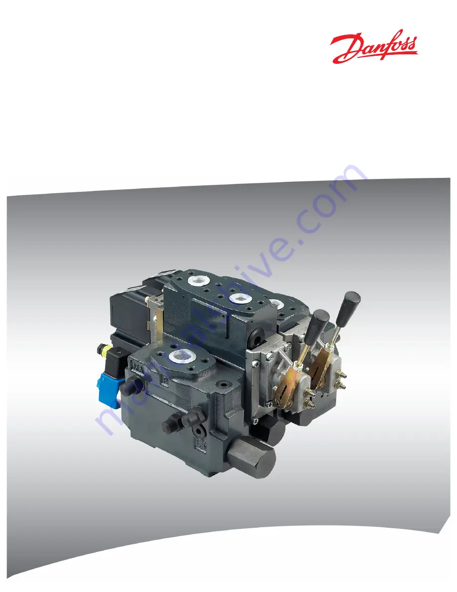
Proportional Valve Group
PVG 120
powersolutions.danfoss.com
Page 1: ...MAKING MODERN LIVING POSSIBLE Technical Information Proportional Valve Group PVG 120 powersolutions danfoss com ...
Page 2: ...ed Rev Mar 2014 Chapters re order Modules selection chart JA Dec 2013 Converted to Danfoss layout DITA CMS ID 2006 2012 Various updates AB IC Apr 2006 New edition AA Technical Information PVG 120 Proportional Valve Group 2 520L0356 Rev JA Mar 2014 ...
Page 3: ...EH Pulse Width Modulation Integrated 20 PVEH Fault Monitoring 20 PVEH connection to fault monitoring output 21 Technical Characteristics General 22 PVP pump side module 22 PVB Basic Module 23 PVLP Shock Valve Characteristic with Pressure Relief Valve 25 PVLP PVLA Suction Function 26 Hydraulic system examples Example of PVG 120 with variable displacement pump 27 Example of PVG 120 with fixed displa...
Page 4: ...C High Current Actuator 37 PVE Electrical Actuation 37 PVT tank side module 38 PVAS Assembly Kit 38 PVG 120 Modules Selection Chart PVG 120 module selection chart 39 Order Specification Ordering of modules for oil flow exceeding 180 l min 47 6 US gal min 43 Order Form 43 Reordering 44 Technical Information PVG 120 Proportional Valve Group Contents 4 520L0356 Rev JA Mar 2014 ...
Page 5: ...ormation 11070179 Basic module for PVBZ Technical Information 520L0721 PVSK module with integrated diverter valve and P disconnect function Technical Information 520L0556 PVPV PVPM pump side module Technical Information 520L0222 Combination module PVGI Technical Information 520L0405 PVSP M Priority module Technical Information 520L0291 Hitch Control System Description User Manual 11036124 11033753...
Page 6: ...f other functions Good regulation characteristics Central pilot supply built in when the valves are actuated electrohydraulically Energy saving Up to eight basic modules per valve group Pump Side Module PVP Built in pressure relief valve System pressure up to 400 bar 5800 psi Pressure gauge connection Versions Open centre version for systems with fixed displacement pumps Open centre version prepar...
Page 7: ... module is always fitted with mechanical actuation PVM which can be combined with the following as required Electrical actuation PVEH proportional high performance 11 32 V PVEO On off 12 V or 24 V Cover for hydraulic remote control PVH Cover for mechanically actuated valve group PVMD Electronic Accessories EHF low adjustment unit EHR ramp generator EHS speed control EHSC closed loop speed control ...
Page 8: ...of 1 162F PVREL electrical control unit 155U PVRES electrical control unit 155B PVRH hydraulic control unit 155N 155N0003 155N0001 155N0004 155N0005 155N0002 Technical Information PVG 120 Proportional Valve Group General Information 8 520L0356 Rev JA Mar 2014 ...
Page 9: ...iting valve saves energy Without LS pressure limiting valve all the oil flow to the working function will be led across the combined shock and suction valves to tank if the pressure exceeds the fixed setting of the valves With LS pressure limiting valve an oil flow of only about 2 l min 0 5 US gal min will be led across the LS pressure limiting valve to tank if the pressure exceeds the valve setti...
Page 10: ...huttle valve 4 Pressure relief valve in PVP 5 Pressure compensator in PVB 6 LS pressure relief valve in PVB 7 Shock and suction valve PVLP 8 Suction valve PVLA 9 Orifice closed center PVP Plug open center PVP 10 LS connection 11 Orifice open center PVP 12 Plug closed center PVP Technical Information PVG 120 Proportional Valve Group PVG 120 sectional view 10 520L0356 Rev JA Mar 2014 ...
Page 11: ...etirmine if any extra requirements for the product design development process production process or maintenance i e the complete product life cycle W Warning All makes brands and types of directional control valves inclusive proportional valves can fail and cause serious damage It is therefore important to analyze all aspects of the application Because the proportional valves are used in many diff...
Page 12: ...h safety logic 2 Emergency stop man present switch 6 PVG 32 control valve group 3 HMI Joystick control 7 Hydraulic deactivation 4 Movement detection sensors W Warning It is the responsibility of the equipment manufacturer that the control system incorporated in the machine is declared as being in confirmity with the relevant machine directives Technical Information PVG 120 Proportional Valve Group...
Page 13: ...ontrol signal neutral OFF Delay 1 2 UDC2 3 4 Error 1 US PVEH with AMP connector 2 UDC2 3 4 Error 1 US PVEH with AMP connector Hydraulic deactivation Neutral detection Supply control signal neutral OFF Delay 1 PVE 1 PVE 2 Emergency stop Man present switch C C D B B A P301 318 A Emergency stop man present switch B PVEH fault monitoring signals C Neutral signal detection D Hydraulic deactivation Tech...
Page 14: ... A PVEH DI AMP connector 4 UDC PVEH DI AMP supply connector AND Hydraulic deactivation high on low off Neutral detection Supply control signal neutral OFF Delay 1 PVE 1 PVE 2 Fault detection Delay DI Logic Memory US DI A DI B 2 4 3 Output Fault detection Delay DI Logic Memory US DI A DI B 2 4 3 Output OR Emergency Stop Man present switch P301 319 System Control Logic e g PLUS 1 for signal monitori...
Page 15: ...9 SUS Max viscosity 460 mm2 s 2128 SUS Filtering Max contamination ISO 4406 See Filtering for more information 23 19 16 Oil consumption in pressure reduction valve for PVT at PVE pilot oil supply 0 4 l min 0 1 US gal min 1 Intermittent operation the permissible values may occur for max 10 of every minute 2 See Order Form for more information regarding the ordering or conversion of valve groups for...
Page 16: ...ack to neutral position Further information can be obtained by contacting the Danfoss Power Solutions Sales Organization 2 Reaction times for PVEH is reduced by 20 by 30 ms if the voltage is not interrupted during the neutral positioning remote control lever without neutral position switch 3 Total oil consumtion for a spool movement from N to full A or B 0 0035 l 0 0009 US gal PVPE electrical reli...
Page 17: ...rrent consumption at rated voltage at 22 C 72 F coil temperature 1 55 A 0 78 A at 85 C 230 F coil temperature 1 0 A 0 5 A Power consumption at 22 C 72 F coil temperature 19 W 19 W at 85 C 230 F coil temperature 12 W 12 W Technical Information PVG 120 Proportional Valve Group Technical Data 520L0356 Rev JA Mar 2014 17 ...
Page 18: ...n 8 W PVEH proportional high PVEH adjusts the main spool position so that it corresponds to an electrical control signal for example from a remote control unit The control signal set point signal is converted into a hydraulic pressure which moves the main spool The position of the main spool is converted in the positional transducer C to an electric signal feed back signal This signal is registere...
Page 19: ... and Range 11 V to 32 V Maximum ripple 5 Current consumption at rated voltage 0 57 0 33 A 12 V 0 3 0 17 A 24 V Signal voltage Neutral 0 5 x UDC A port B port 0 25 UDC to 0 75 UDC Signal current at rated voltage 0 25 mA to 0 70 mA Input impedance in relation to 0 5 UDC 12 KΩ Input capacitor 100 ηF Power consumption 7 3 5 W PVEH Maximum load 100 mA 60 mA Reaction time at fault Active Passive 500 ms ...
Page 20: ...l spool position is further than the demanded spool position 12 PVEA 25 the system detects an error and will switch into an active error state On the other hand a situation where the actual position is closer to neutral than that demanded will not cause an error state This situation is considered in control When an active error state occurs the fault monitoring logic will be triggered Active fault...
Page 21: ...y required for the system See Safety in Application for more information about different degrees of safety PVEH connection to fault monitoring output Normal Fault Transistor output function Green Transistor output function Red A External relay B Solenoid valve e g PVPE A External relay B Solenoid valve e g PVPE Via an external relay pin 3 can be connected to an electrically actuated valve which wi...
Page 22: ...e of 50 C 122 F was used PVP pump side module PVP pressure relief valve characteristic The pressure relief valve is adjustable within the 50 400 bar 725 6225 psi range by means of a screw PVP neutral flow pressure in PVP open center U PVP for PVB oil flow 180 l min 47 6 US gal min S PVP standard Technical Information PVG 120 Proportional Valve Group Technical Characteristics 22 520L0356 Rev JA Mar...
Page 23: ... US gal min D 180 l min 47 6 US gal min D I 240 l min 63 4 US gal min D II 210 l min 55 5 US gal min Closed center system with basic module for oil flow 180 l min 47 6 US gal min Open center system with basic module for oil flow 180 l min 47 6 US gal min and pump side module 155G5027 155G5028 155G5029 Technical Information PVG 120 Proportional Valve Group Technical Characteristics 520L0356 Rev JA ...
Page 24: ...tral position spools with open neutral position p The oil flow Q is shown as a function of the load p Pressure drop A B T at full spool travel Technical Information PVG 120 Proportional Valve Group Technical Characteristics 24 520L0356 Rev JA Mar 2014 ...
Page 25: ...e Relief Valve PVLP shock valve characteristic with Pressure Relief Valve The shock valve PVLP is designed to absorb shock effects Consequently it shall not be used as a pressure relief valve Technical Information PVG 120 Proportional Valve Group Technical Characteristics 520L0356 Rev JA Mar 2014 25 ...
Page 26: ...PVLP PVLA Suction Function PVLP PVLA suction function characteristic Technical Information PVG 120 Proportional Valve Group Technical Characteristics 26 520L0356 Rev JA Mar 2014 ...
Page 27: ...ple of PVG 120 with variable displacement pump Example of PVG 120 with variable displacement pump Technical Information PVG 120 Proportional Valve Group Hydraulic system examples 520L0356 Rev JA Mar 2014 27 ...
Page 28: ...xample of PVG 120 with fixed displacement pump Example of PVG 120 with fixed displacement pump Technical Information PVG 120 Proportional Valve Group Hydraulic system examples 28 520L0356 Rev JA Mar 2014 ...
Page 29: ...ions being adapted to the recommendations of the oil supplier Before using other biodegradable fluids please consult the Danfoss Power Solutions Sales Organisation Particle Content Degree of Contamination Oil filtration must prevent the particle content from exceeding an acceptable level i e an acceptable degree of contamination Maximum contamination for PVG 120 is 23 19 16 see ISO 4406 Calibratio...
Page 30: ...t large particles Such particles can appear in the system as a result of pump damage hose fracture use of quick couplings filter damage starting up contamination etc The filter that protects the pilot supply in the tank side module has a mesh of 125 µm It is obtainable as a spare part and is easy to replace The filter protecting the essential PVE parts has a mesh of 125 µm Conversion Factors 1 N m...
Page 31: ... 98 158 6 22 PG 9 on off PG 11 prop DIN 43650 V310153 B 35 5 max 262 5 10 335 111 4 37 25 0 98 27 1 06 15 0 59 1 46 1 398 1 319 1 319 1 10 23 8 0 937 1 094 38 1 50 2 000 PVB 1 2 3 4 5 6 7 8 L mm in 170 6 69 237 9 33 304 11 97 371 14 61 438 17 24 505 19 88 572 22 51 639 25 16 L1 mm in 263 5 10 38 330 5 13 02 397 5 15 66 464 5 18 30 531 5 20 94 598 5 23 58 665 5 26 22 732 55 28 86 L2 mm in 255 10 05...
Page 32: ...0 17 mm deep 3 8 16 UNC 0 7 in deep M M12 18 mm deep 7 16 14 UNC 0 7 in deep N G 3 8 3 4 16 UNF PVG 120 Outline dimensions 31 5 1 240 14 49 32 1 25 F 13 0 51 108 5 4 272 27 62 99 3 90 PVH PVMD PVH PB PA 120 4 72 141 5 55 max 372 5 14 665 77 3 03 max 284 11 18 23 0 91 48 5 1 909 48 5 1 909 1 06 2 44 0 55 1 93 V310103 A 0 413 1 791 10 5 45 5 F G 1 4 1 2 20 UNF Dimensions in parenthesis apply to high...
Page 33: ... 37 5 Base with an angle of 22 5 37 5 67 5 9 7 5 1 2 7 5 1 5 7 5 187 5 1 9 5 19 5 V310018 A 22 5 52 5 82 5 1 1 2 5 1 4 2 5 17 2 5 19 5 19 5 V310014 A Technical Information PVG 120 Proportional Valve Group Dimensions 520L0356 Rev JA Mar 2014 33 ...
Page 34: ...022 Closed center PVPV without pressure relief valve For pumps with variable displacement Pressure gauge connection Metric flange 155G5030 SAE flange 155G5032 O ring boss 155G5031 Port connections P 1 in SAE flange 415 bar 11 16 12 UN O ring Boss 6020 psi MA G 1 4 1 2 20 UNF O ring Boss LS G 3 8 3 4 16 UNF O ring Boss PVP Accessories for Open Center Pump Side Modules Symbol Description Code number...
Page 35: ...G6006 PVB Accessories for Basic Modules Symbol Description Code number PVBP plug 155G6081 PVBU module for oil flow exceeding 180 l min 47 6 US gal min Connection for external LS pressure relief 155G6035 PVBC connection for external LS pressure relief 155G6082 PVBR LS pressure relief valve for ports A B port 155G6080 Port connection G 1 4 available with G 1 4 thread only PVLA Suction Valve Symbol C...
Page 36: ... l min 25 1 US gal min C 130 l min 34 3 US gal min D1 180 l min 47 6 US gal min 4 way 3 position Closed neutral position 155G6452 155G6454 155G6456 155G6458 4 way 3 position Throttled open neutral position 155G6464 155G6466 155G6468 3 way 3 position P B 155G6476 155G6478 1 Main spool D is used for oil flow exceeding 180 l min 47 6 US gal min PVM Mechanical Actuation PVM Mechanical Actuation Symbol...
Page 37: ...V 11110598 PVE Electrical Actuation Symbol Description Code number Hirschmann AMP Deutsch PVEO ON OFF 12 V 155G4272 155G4282 11110601 24 V 155G4274 155G4284 11110652 PVEH Proportional high Puls width modulation short reaction time low hysteresis active fault monitoring inductive transducer 155G4092 155G4094 PVEH Proportional high Puls width modulation short reaction time low hysteresis passive fau...
Page 38: ... Mounting thread metric 155G7040 Mounting thread UNF 155G7042 Lower part of PVH pilot oil supply for hydraulic actuations Filter mesh 125 µm Mounting thread metric 155G7043 Mounting thread UNF 155G7044 Port connections T 1 in SAE flange 210 bar 15 16 12 UN O ring Boss 3045 psi PP G 3 8 3 4 16 UNF O ring Boss LX G 3 8 3 4 16 UNF O ring Boss PVAS Assembly Kit Code number 155G Nr of modules 1 PVB 2 P...
Page 39: ...s Metric flange Weight kg lb Facilities for shock valves AB 155G6007 155G6006 155G6005 10 2 22 5 PVB low basic module SAE flange O ring Boss Metric flange Weight kg lb No facilities for shock valves AB 155G6016 155G6015 155G6014 8 9 19 6 Technical Information PVG 120 Proportional Valve Group PVG 120 Modules Selection Chart 520L0356 Rev JA Mar 2014 39 ...
Page 40: ... 155G3040 155G3041 22 5 37 5 PVM PVH 155G3050 155G3051 22 5 37 5 Weight kg lb 0 5 1 1 PVMD cover for PVM Code number Weight kg lb 155G4061 0 3 0 7 PVT tank side module Code number SAE flange O ring Boss Metric flange Weight kg lb Upper part excl LX connection 155G7022 155G7021 155G7020 4 6 10 1 Upper part incl LX connection 155G7025 155G7024 155G7023 Lower part incl pilot oil supply for PVE 155G70...
Page 41: ... valve PVH 155G5061 0 5 1 1 Electrical relief valve PVPE 12 V 155G5052 0 7 1 5 24 V 155G5054 PVH cover for PVRHH Port Code number Weight kg lb 1 2 in 20 UNF 155G4021 0 4 0 9 G 1 4 155G4022 PVE electrical actuation Connector PVEH fault monitoring PVEO voltage Active Passive 12 V 24 V Hirschmann 155G4092 155G4093 155G4272 155G4274 AMP 155G4094 155G4095 155G4282 155G4284 Weight kg lb 1 25 2 76 1 2 2 ...
Page 42: ...G0325 350 5100 155G0350 375 5400 155G0375 400 5800 155G0400 Weight kg lb 0 175 0 386 PVAS assembly kit PVB s 1 2 3 4 5 6 7 8 Code number 155G8031 155G8032 155G8033 155G8034 155G8035 155G8036 155G8037 155G8038 Weight kg 0 8 1 0 1 1 1 2 1 4 1 7 1 9 2 1 lb 1 8 2 2 2 4 2 6 3 1 3 7 4 2 4 6 Technical Information PVG 120 Proportional Valve Group PVG 120 Modules Selection Chart 42 520L0356 Rev JA Mar 2014...
Page 43: ...t 1 Ordering Order accessory module 155G6035 and main spool D 2 Conversion In closed center systems a max oil flow exceeding 180 l min 47 6 US gal min can be achieved by changing the following basic module parts The spring behind the pressure compensator The plug behind the pressure compensator The code number of the spring and plug is 155G6035 PVBU accessory module Order Form An order form for PV...
Page 44: ... to fill in The code number for the whole of the specified valve group PVG No is entered here In the event of a repeat order all you have to do is enter the number Danfoss has given on the initial confirmation of order If PVG 120 is to be used with phosphate esters this must be stated on the order form See Non flammable Fluids for more information Technical Information PVG 120 Proportional Valve G...
Page 45: ...Technical Information PVG 120 Proportional Valve Group Order Specification 520L0356 Rev JA Mar 2014 45 ...
Page 46: ...Technical Information PVG 120 Proportional Valve Group 46 520L0356 Rev JA Mar 2014 ...
Page 47: ...Technical Information PVG 120 Proportional Valve Group 520L0356 Rev JA Mar 2014 47 ...
Page 48: ...ark Phone 45 7488 2222 Danfoss Power Solutions US Company 2800 East 13th Street Ames IA 50010 USA Phone 1 515 239 6000 Danfoss Power Solutions Shanghai Co Ltd Building 22 No 1000 Jin Hai Rd Jin Qiao Pudong New District Shanghai China 201206 Phone 86 21 3418 5200 Danfoss can accept no responsibility for possible errors in catalogues brochures and other printed material Danfoss reserves the right to...