1
FRCC.EI.019.A2.ML © Danfoss Commercial Compressors 06/12
Instructions
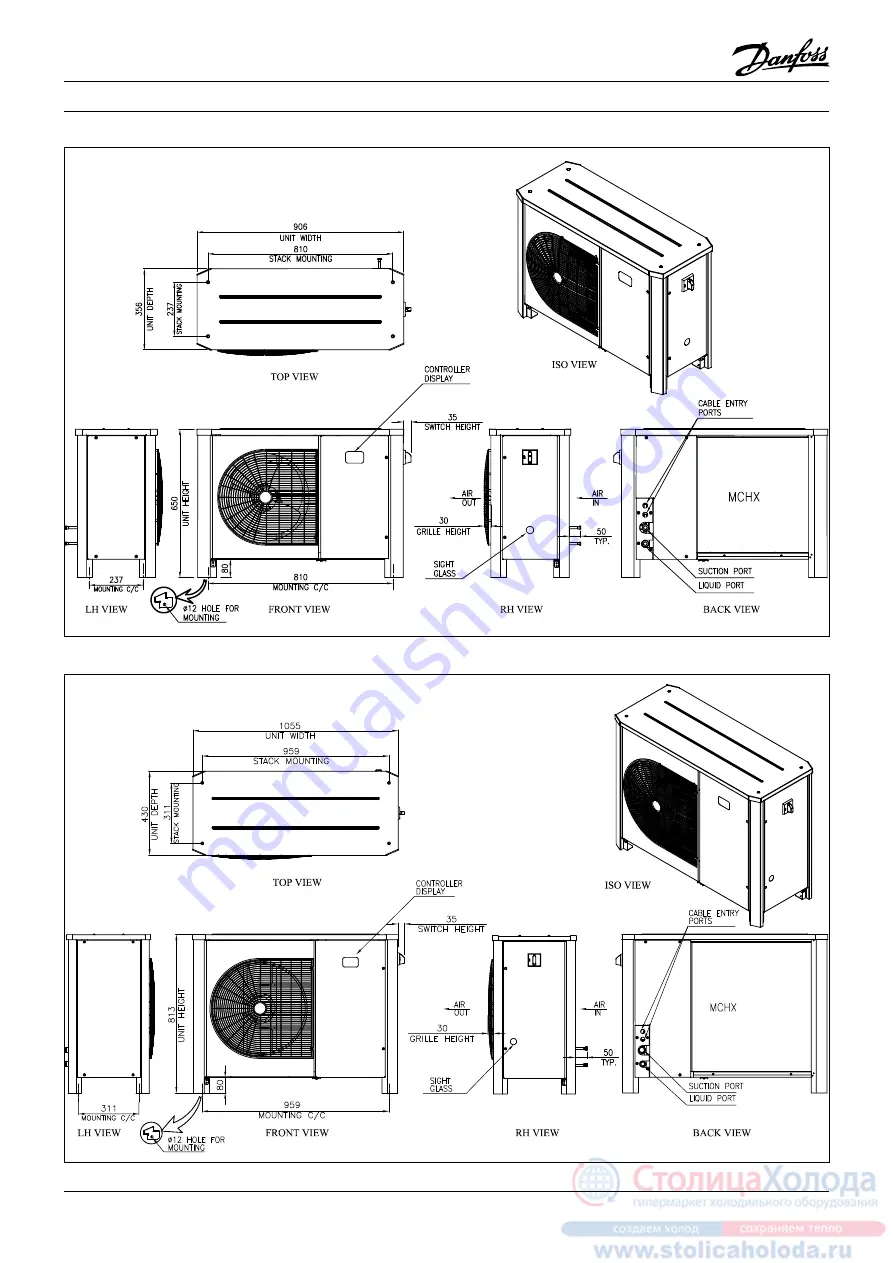
OP-LPHM018-026 & OP-MPHM007-010-012-015-018
OP-LPHM048-068 & OP-MPHM026-034 & OP-MPUM034-046 & OP-MPGM034
Page 1: ...1 FRCC EI 019 A2 ML Danfoss Commercial Compressors 06 12 Instructions OP LPHM018 026 OP MPHM007 010 012 015 018 OP LPHM048 068 OP MPHM026 034 OP MPUM034 046 OP MPGM034 ...
Page 2: ...P VIEW 966 UNIT HEIGHT FRONT VIEW 35 SWITCH HEIGHT MOUNTING Ø12 HOLE FOR SIGHT 50 TYP DISPLAY CONTROLLER PORTS CABLE ENTRY LIQUID PORT SUCTION PORT MCHX RH VIEW BACK VIEW ISO VIEW LH VIEW 479 MOUNTING C C 80 GLASS 1702 MOUNTING C C OP LPHM215 271 OP MPUM125 162 Instructions OP LPHM096 136 OP MPUM068 080 107 ...
Page 3: ...se instructions and sound refrigeration engineering practice relating to installation commissioning maintenance and service A Model B Code number C Refrigerant D Supply voltage Locked Rotor Ampere Maxi mum Current Consumption E Application F Protection G Housing Service Pressure H Serial Number and bar code I Mounting holes for stack mounting J Electronic controller display K Main switch L Cable e...
Page 4: ... in picture 2 Slowly release the nitrogen holding charge through the schrader port Connect the unit to the system as soon as pos sible to avoid oil contamination from ambient moisture Avoid material entering into the system while cutting tubes Never drill holes where burrs cannot be removed Braze with great care using state of the art technique and vent piping with nitrogen gas low Connect the req...
Page 5: ...s is provided observe the oil level at start and during operation to conirm that the oil level remains visible Respect the operating limits Check all tubes for abnormal vibration Move ments in excess of 1 5 mm require corrective measures such as tube brackets When needed additional refrigerant in liquid phase may be added in the low pressure side as far as possible from the compressor The com pres...
Page 6: ...stle Do not use a wire brush Do not impact or scrape the coil with the vacuum tube or air nozzle Before closing the fan door turn the fan blade in the position shown in picture 6 to avoid that the door hits the fan If the refrigerant system has been opened the system has to be lushed with dry air or nitrogen to remove moisture and a new ilter drier has to be installed If evacuation of refrigerant ...
Page 7: ...at optional X1 Terminal Supply Supply Fan Fan Alarm Alarm Comp Compressor CCH Crankcase Heater Aux Auxiliary P U B1 P U B2 T S1 M 1 M2 R5 P B4 P B3 K2 F1 N L1 I I I 2 4 6 Q1 COM NC NO K2 C1 C2 M 1 M1 K1 R1 R2 R3 C3 WD2 DI1 DI2 S1 S2 S3 S4 S5 AO1 Display EKA S6 s Alarm Comp Fan CCH AUX 230Vac 230Vac L L N PE PE DI3 230Vac out Supply Fan Optyma Plus Controller RS485 A B A1 R4 Code G OP LPHM026 048 0...
Page 8: ...Plus Controller RS485 A B A1 M 1 M2 M 1 M3 C3 C4 L1 L2 L2 N N X1 S2 0 10V U L N A2 A1 Optyma Plus Controller A2 Fan Speed Controller B1 Condensing Pressure Transducer B2 Suction Pressure Transducer B3 High Pressure Switch B4 Low Pressure Switch C3 Run Capacitor Fan 1 C4 Run Capacitor Fan 2 F1 Fuse Control Circuit K2 Contactor M1 Compressor M2 Fan Motor 1 M3 Fan Motor 2 Q1 Main Switch R1 Ambient Te...