Service Manual
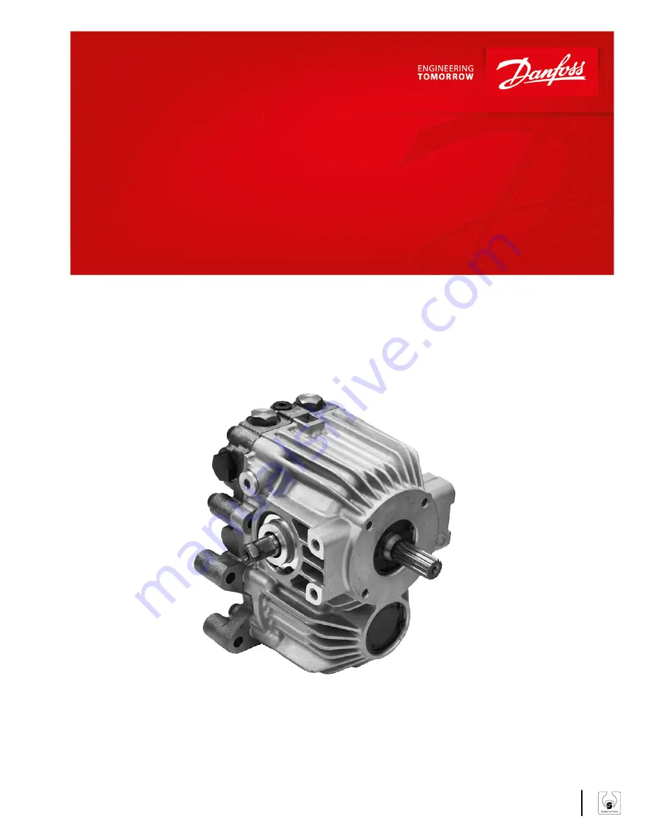
LDU 20
Closed Circuit Axial Piston Transmission
powersolutions.danfoss.com
Page 1: ...Service Manual LDU 20 Closed Circuit Axial Piston Transmission powersolutions danfoss com ...
Page 2: ...s Date Changed Rev July 2017 Updated to Engineering Tomorrow 0202 March 2014 Danfoss layout BA January 2011 First edition AA Service Manual LDU 20 Closed Circuit Axial Piston Transmission 2 Danfoss July 2017 11071687 AX00000049en US0202 ...
Page 3: ...ve 11 Control 12 Direct Displacement Control 12 Control Handle Requirements 12 Operating Parameters Overview 13 Input Speed 13 System Pressure 13 Input Power 13 Charge Pressure 13 Case Pressure 14 Viscosity 14 Temperature 14 Technical Specifications General Specifications 15 Physical Properties 15 Operating Parameters 15 Fluid Specifications 15 Fluid and Filter Maintenance Fluid and Filter Recomme...
Page 4: ...r proper charge check HPRV operation 22 Minor Repair Shaft Seals 23 Removal 23 Inspection 23 Assembly 23 Charge Check HPRV 24 Removal 25 Inspection 25 Reassembly 25 Bypass Valve 25 Removal 25 Inspection 25 Reassembly 25 Torque Chart Plug Size and Torque Chart 27 Service Manual LDU 20 Closed Circuit Axial Piston Transmission Contents 4 Danfoss July 2017 11071687 AX00000049en US0202 ...
Page 5: ...es Remove the unit Prior to performing major repairs remove the unit from the vehicle machine Chock the wheels on the vehicle or lock the mechanism to inhibit movement Be aware that hydraulic fluid may be under high pressure and or hot Inspect the outside of the pump and fittings for damage Cap hoses and plug ports after removal to prevent contamination Keep it clean Cleanliness is a primary means...
Page 6: ...e W Warning Escaping hydraulic fluid under pressure can have sufficient force to penetrate your skin causing serious injury and or infection This fluid may also be hot enough to cause burns Use caution when dealing with hydraulic fluid under pressure Relieve pressure in the system before removing hoses fittings gauges or components Never use your hand or any other body part to check for leaks in a...
Page 7: ...cation Parallelism specification Cover splines with installation cylinder Mark orientation for reinstallation The symbols above appear in the illustrations and text of this manual They are intended to communicate helpful information at the point where it is most useful to the reader In most instances the appearance of the symbol itself denotes its meaning The legend above defines each symbol and e...
Page 8: ...ete Hydrostatic Transmission package for Turf care machine Compact Utility Tractor of up to 22kw 30PS Compact design U style layout in One housing with Z shaft configuration Available external charge Bypass valve for the pulling of the vehicle Same shaft center distance as BDU21 85mm Between pump and motor shaft Same drive line design is available between BDU21 and LDU20 Best in class Efficiency b...
Page 9: ...Heat exchanger HPRV valves Filter Charge relief valve Charge pump Heat exchanger bypass Fixed displacement motor Output shaft Cylinder block assembly P400003 Schematic Diagram MA1 MB1 MA2 MB2 L1 L2 L3 S M3 P400004 Service Manual LDU 20 Closed Circuit Axial Piston Transmission General Description Danfoss July 2017 11071687 AX00000049en US0202 9 ...
Page 10: ...h leads to elevated HPRV flow will cause a pressure rise with flow above a valve setting Consult factory for application review Charge Check Relief Valve with Orifice As an option LDU20 offers a charge check relief valve with an orifice in order to enlarge the neutral dead band In some applications it is desirable to use charge check valve with orifice for expanding null dead band giving both the ...
Page 11: ...em Pressure P400006 CPRV Charge Pressure Relief Valve The charge pressure relief valve maintains charge pressure at a designated level above case pressure The charge pressure relief valve is a direct acting poppet valve which opens and discharges fluid to the HST case when pressure exceeds a designated level For external charge flow the CPRV is set according to below table The charge pressure reli...
Page 12: ... trunnion torque is 79 1 N m 700 lbf in The approximate torque necessary to rotate the control per 300 bar and 3000 rpm of system operating pressure is 25 N m with standard valveplate The actual value will vary due to the influence of pump operating conditions For mating dimensions see Installation drawings in LDU20 Technical Information Manual 11071631 W Warning With no external forces applied to...
Page 13: ...gh system pressure which results from high load reduces expected life Hydraulic unit life depends on the speed and normal operating or weighted average pressure that can only be determined from a duty cycle analysis Maximum working pressure is the highest recommended application pressure Maximum working pressure is not intended to be a continuous pressure Propel systems with application pressures ...
Page 14: ...occur at cold start Limit speeds until the system warms up Refer to Fluid specifications in LDU20 Technical Information Manual 11071631 Temperature Maintain fluid temperature within the limits shown in the Technical Specifications section of LDU20 Technical Information Manual 11071631 Minimum temperature relates to the physical properties of the component materials Cold oil will not affect the dur...
Page 15: ...volume Case only liter US gal 1 1 0 28 With passage liter US gal 1 2 0 32 Port Configuration High pressure gauge port SAE O ring boss 3 4 16 UNF Charge pressure gauge port SAE O ring boss 9 16 18 UNF Case drain ports SAE O ring boss 3 4 16 UNF Operating Parameters Features Units LDU20 Input speed Minimum for full performance min 1 rpm 500 Rated 3400 Maximum 3800 System Pressure Maximum working bar...
Page 16: ...nliness per ISO 4406 22 18 13 Efficiency charge pressure filtration b ratio b 15 20 75 b 10 10 Efficiency suction and return line filtration b 15 20 75 b 10 10 Rercommended inlet screen mesh size µm 100 125 Service Manual LDU 20 Closed Circuit Axial Piston Transmission Technical Specifications 16 Danfoss July 2017 11071687 AX00000049en US0202 ...
Page 17: ... of operation Fluid and Filter Change Interval Reservoir Type Max Oil Change Interval Sealed 2000 Hours Breather 500 Hours C Caution High temperatures and pressures accelerate fluid aging This may require more frequent fluid changes Change the fluid more frequently if it becomes contaminated with foreign matter dirt water grease etc or if the fluid is subjected to temperature levels greater than t...
Page 18: ...ar psi L1 L2 3 4 16 UNF 5 16 internal hex Case Drain 10 100 MA1 MA2 MB1 MB2 3 4 16 UNF 7 8 hex wrench System Pressure 500 5000 M3 9 16 18 UNF 1 4 internal hex Charge Pressure 50 1000 Port Locations M3 L1 L2 REVERSE SIDE P108517 MB1 MB2 REVERSE SIDE MA1 MA2 REVERSE SIDE Service Manual LDU 20 Closed Circuit Axial Piston Transmission Pressure Measurements 18 Danfoss July 2017 11071687 AX00000049en US...
Page 19: ...e may damage hydraulic components Check carefully for inlet line leaks Do not run at maximum pressure until system is free of air and fluid has been thoroughly filtered 8 Use a common method to disable the engine to prevent it from starting Crank the starter for several seconds Do not to exceed the engine manufacturer s recommendation Wait 30 seconds and then crank the engine a second time as stat...
Page 20: ...t in system Measure system pressure If pressure is too high reduce loads Transmission Operates Normally in One Direction Only Item Description Action Control linkage Control linkage is operating improperly Repair replace linkage Interchange charge check HPRVs Interchanging the charge check HPRVs will show if the problem is related to the valve function If the problem changes direction replace the ...
Page 21: ...igned pump and prime mover shafts create noise Align shafts Charge check HPRVs Unusual noise may indicate sticking valves Possible contamination Clean replace valves and test pump Sluggish System Response Item Description Action Oil level in reservoir Low oil level causes sluggish response Fill reservoir Charge check HPRVs Incorrect pressure settings affects system reaction time Replace charge che...
Page 22: ... of system contamination such as oil discoloration foam in the oil sludge or small metal particles 4 Remove the transmission C Caution Be careful not to damage solenoids and electrical connections when using straps or chains to remove transmission from machine 5 Perform transmission function test 6 Before re installing the transmission on the machine test for leaks drain the system flush all lines...
Page 23: ...ines with protective sleeve to avoid damaging the seal during installation 2 Using a seal installation tool start the seal into the housing bore Hand press the seal the rest of the way into the housing bore Ensure the seal clears the retaining ring groove in the housing Remove the protective sleeve from the shaft Do not press seal beyond snap ring groove Stop pressing just when you have room to in...
Page 24: ...pressure relief and charge check valve assembly may be removed for cleaning and replacement of the O rings These valves are factory set and are not field adjustable Refer to the pump model code for the factory setting when ordering replacements Service Manual LDU 20 Closed Circuit Axial Piston Transmission Minor Repair 24 Danfoss July 2017 11071687 AX00000049en US0202 ...
Page 25: ...e each valve assembly moves freely in its bore 3 Install the valve seat plugs into the center section and torque to 78 4 N m 58 lbf ft 4 Operate vehicle machine through full range of controls to ensure proper operation Check for leaks Charge Check HPRV P108 167E 78 4 Nm 58 lbf ft 78 4 Nm 58 lbf ft N120 24 mm N130 N100 N110 P120 24 mm P130 P100 P110 Bypass Valve Removal Using a 17mm hex wrench remo...
Page 26: ...using a 17mm hex wrench Torque to 12 N m 9lbf ft Bypass Valve P108 166E 12 Nm 9 lbf ft M100 17 mm M110 M120 M130 Service Manual LDU 20 Closed Circuit Axial Piston Transmission Minor Repair 26 Danfoss July 2017 11071687 AX00000049en US0202 ...
Page 27: ...57 8 J400 9 16 18 UNF 1 4 internal hex 35 25 8 Y300 3 4 16 UNF 5 16 internal hex 39 2 29 Plugs J400 J200 J250 J300 J350 L1 L2 REVERSE SIDE Y300 Y300 P108482 MB1 M3 MA1 MB2 MA2 REVERSE SIDE REVERSE SIDE Service Manual LDU 20 Closed Circuit Axial Piston Transmission Torque Chart Danfoss July 2017 11071687 AX00000049en US0202 27 ...
Page 28: ...olutions ApS Nordborgvej 81 DK 6430 Nordborg Denmark Phone 45 7488 2222 Danfoss Power Solutions US Company 2800 East 13th Street Ames IA 50010 USA Phone 1 515 239 6000 Danfoss Power Solutions Trading Shanghai Co Ltd Building 22 No 1000 Jin Hai Rd Jin Qiao Pudong New District Shanghai China 201206 Phone 86 21 3418 5200 Danfoss can accept no responsibility for possible errors in catalogues brochures...