


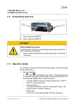


3.5 Operation and display elements C.2
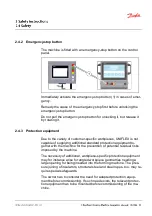
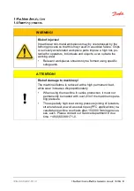
(1) Emergency-stop button
(2) Illuminated Motor on button
(3) Motor off button
(4) Illuminated foot switch
(5) Illuminated Open tool button
(6) Illuminated Close tool button
(7) Locking lever / angle setting
(8) control panel of CONTROL C.2
The illuminated buttons
and
may be arranged the other way
round, depending on the control version.
The operation of the control system CONTROL C.2 is described in
a separate Operation Manual. This description is supplied with the
machine.
Summary of Contents for ET5070
Page 1: ......
Page 3: ......
Page 65: ......
Page 82: ...Retaining bolt Crimping die profile 262 263 239 266 232 237 554 245 246 247 245 114 4 x x x...
Page 83: ...9 8 Hydraulic diagram...
Page 84: ......
Page 85: ...9 9 Electric diagram...
Page 86: ......
Page 87: ......
Page 88: ......
Page 89: ......
Page 90: ......
Page 93: ......
Page 94: ......
Page 95: ......
Page 96: ......