


If the superheat fluctuates
When the refrigerating system has been made to work steadily,
the controller’s factory-set control parameters should in most
cases provide a stable and relatively fast regulating system.
If the system, however, fluctuates this may be due to the fact that
superheat parameters that are too low have been selected. Before
starting any adjustment of the factory settings check the S2 sensor
location – see page 9:
If adaptive superheat has been selected (n21 = 1):
Adjust: n09, n10 and n18.
If load-defined superheat MSS has been selected (n21 = 2):
Adjust: n09, n10 and n22.
Alternatively it may be due to the fact that the set regulation
parameters are not optimal.
If the time of oscillation is longer than the integration time:
(T
p
> T
n
(T
n
is e.g. 240 seconds))
1. Increase T
n
to 1.2 times T
p
2. Wait until the system is in balance again
3. If there is still oscillation, reduce K
p
by e.g. 20%
4. Wait until the system is in balance
5. If it continues to oscillate, repeat 3 and 4
If the time of oscillation is shorter than the integration time:
(T
p
< T
n
(T
n
is e.g. 240 seconds))
1. Reduce K
p
by e.g. 20% of the scale reading
2. Wait until the system is in balance
3. If it continues to oscillate, repeat 1 and 2.
©Danfoss A/S (AC-MCI / sw), 2014-03
DKRCC.PS.RP0.A1.02/520H7142
15
14
DKRCC.PS.RP0.A1.02/520H7142
©Danfoss A/S (AC-MCI / sw), 2014-03
Manual Superheat controller type EKD 316
Manual Superheat controller type EKD 316
Finding the optimum settings
Details on the controller algorithm and settings
Kp factor (n04) and Kp min (n19)
The Proportional Gain is dependent on the value of the measured
superheat SH relative to Reference superheat SH ref. The
Proportional Gain has the following values relative to superheat SH:
If SH is more than 2.5K greater than SH ref, then Gain equals Kp
factor.
If SH is within the range -0.5 and 2.5K from SH ref, then Gain equals
Kp factor times Kp min.
The reason for this variable Gain is to provide stable superheat for
values near the superheat reference.
Note:
The value of Gain does not change suddenly but gradually when
SH gets close to SH ref.
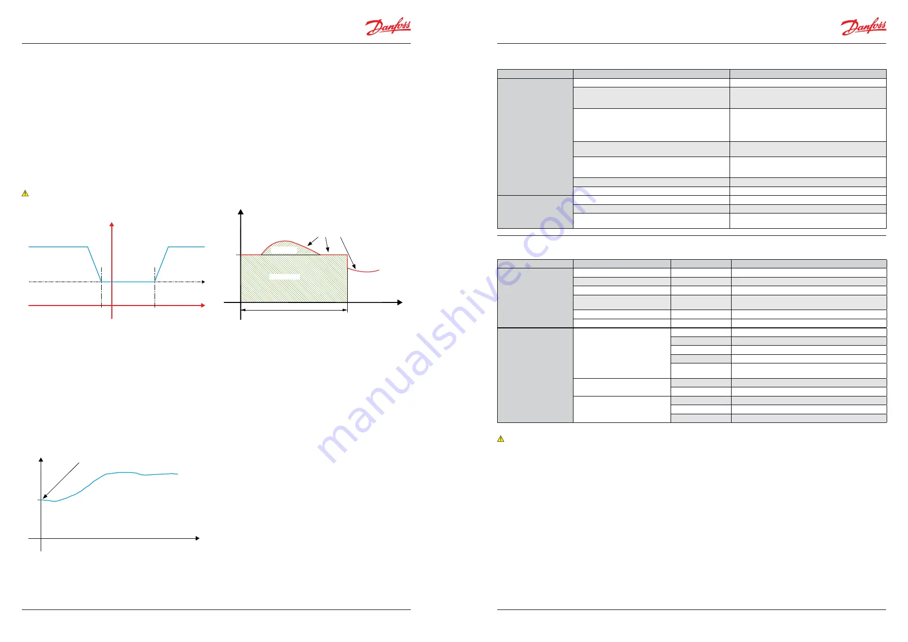
Initial "Kick start" startup
In general the valve opening degree is controlled by the measured
value of the superheat SH. This means that during certain
situations during startup, the valve will be slow to open due to
the built-up of superheat from a small value. To prevent this from
happening, the valve is given an initial opening degree dependent
on the Kp factor, the measured superheat SH and SH close, as
given in the following relationship:
Initial OD% = kp factor*(SH – SH close)
This procedure is not to be confused with the force opening of the
valve given in the “Problems with startup” section.
Dan
fo
ss
84N375.11
Dan
fo
ss
84N376.11
Problems with startup
Sometimes in one-to-one applications, the valve does not open
sufficiently on startup, and troublesome low pressure trips may
occur. This problem is typical when using the single loop control
where only the SH controls the opening of the valve.
The
force opening of valve
function has been implemented in
the EKD 316 controller. After startup, this function will provide a
constant, set minimum opening degree during a set time period,
regardless of the superheat value. The setting parameters are
called
Start OD%
(n17) and
StartUp time
(n15).
Please observe that the
Start OD%
is a minimum value after
startup and if the measured superheat (u21) produces a value
greater than
Start OD%
then the value will be valve opening
degree (u24) – see the diagram.
Dan
fo
ss
84N378.11
Troubleshooting
Symptom
Possible Cause
Remedy
Suction pressure too low
Pressure drop across the evaporator too high
Lack of subcooling ahead of expansion valve
Check refrigerant ahead of expansion valve.
If the valve is placed much higher than condenser outlet,
check pressure difference.
Evaporator superheat too high
1. Check superheat performance, the settings
SH min and SH max.
2. Check valve capacity.
3. Check that the maximum number of steps of
valve is same as parameter n37.
Pressure drop across the expansion valve less than valve is
sized for
Check pressure drop across expansion valve. Replace with
larger valve.
Expansion valve too small
Check refrigeration system capacity and compare with
expansion valve capacity. Replace with larger valve if
necessary.
Expansion valve block with foreign material
Remove valve and examine the orifice.
Evaporator wholly or partly iced up
De-ice evaporator
Liquid hammer
in compressor
Superheat of expansion valve too low
Increase the values of SH close and SH min.
Superheat reference set too low
Increase the value of SH min
The S2 sensor not in good contact with the suction line
Ensure that S2 sensor is secured on suction line. Insulate
sensor.
Alarms
Symptom
Possible Cause
Fault Message
Remedy
All Light emitting diodes
flashing
E24
S2 sensor fault
E25
S4 sensor fault
Analog input outside range.
E19
Pressure transmitter outside range.
E20
Check pressure transmitter, connections at 14-15 and
pressure.
No refrigerant selected
A11
Select refrigerant
Battery alarm
A44
Check the battery voltage is the nominal voltage.
The controller can give the
following messages
Error message
E1
Fault in controller
E24
S2 Sensor error
E25
S4 Sensor error
E19
The input signal on terminals 21-22 is outside the range.
E20
The input signal on terminals 17-19 is below
minumum limit (P0 signal)
Alarm message
A11
No refrigerant has been selected
A44
Battery alarm (no voltage or too low voltage)
Status codes
S5
MOP
S10
Refrigeration stopped r12=off
non
Regulation, no fault
Note:
1. Only one alarm is displayed at a time in the controller display and are shown in the
order given above. All alarms are displayed in the AKM system.
2. The alarm E19 will only be active if address o10 is set to 1 or more.
3. EKD 316 with change over relay ( 3 terminals 24-25-26)
4. The battery alarm A44 is only active when battery alarm address A34 is set to ON.
Proportional Gain
Reg.OD%
OD%
Start OD%
Start
Start Up time*
Time from start
Normal Reg.
Valve OD%
Forced OD%
Kp factor
Kp factor multiplied Kp min.
SH ref
-0.5
2.5
SH
Start
Time
Kp factor* (SH - SH Close)
When Kp factor = 3, SH = 12, Close = 2
Initial OD % = 30%
OD%