


Operation
Superheat function
You may choose between two kinds of superheat regulation,
either:
Minimum stable superheat (MSS)
Load-defined superheat
The regulation modes for controlling superheat
There are two different ways of controlling superheat, i.e.
controlling according to the minimum stable superheat (MSS) and
Load Defined superheat.
The parameter SH mode selects the controlling form where it can
be set to MSS when set to 1, or Load Defined superheat when set
to 2.
Minimum stable superheat (MSS)
The superheat control algorithm will attempt to regulate the
superheat down to the lowest stable value between the minimum
superheat setting, "Min SH" and the maximum superheat setting,
"Max SH".
The superheat reference SH ref is adaptive and adjusted.
When using this form of control, there are three settings that have
major affect on this mode of control.
Max SH – The maximum limit of SH ref.
Min SH – The minimum limit of SH ref. Care should be taken not
to set this value too low in order to avoid flooding back into the
compressor.
Stability – This factor determines how much instability can be
accepted. Small values will cause the SH ref to increase if the
slightest instability in SH is detected. Higher values will accept a
higher degree of instability.
Function
Parameter
Default value
Superheat control -MSS
n21
1
Min Superheat Reference
n10
1 - 12 K
Max Superheat Reference
n09
2 - 15 K
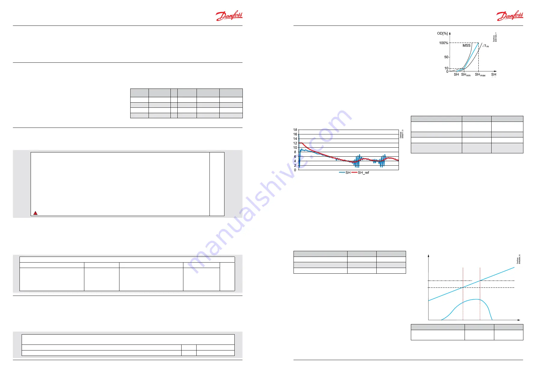
Load define application
SH ref follows a defined curve as shown below. This curve is
defined by three values: SH close SH max and SH min.
This form of regulation is similar to the thermostatic valve where
the spring force can be adjusted to keep the SH (superheat) in the
stable region to the right of the curve.
The advantage over the thermostatic valve is that there are three
settings to define the operating curve.
The reference follows a defined curve. This curve is defined by
three values: the closing value, the min. value and the max. value.
These three values must be selected in such a way that the curve
is situated between the MSS curve and the curve for average
temperature difference
∆
Tm (temperature difference between
media temperature and evaporating temperature.
Setting example = n22=4, n10=6 and n09=10 K).
Function
Parameter
Value
Superheat control mode -2
= Load define
n21
2
Min Superheat Reference
n10
1 K
Max Superheat Reference
n09
2 K
Value of min. SH ref for loads
under 10%
n22
Must be between
Min and Max SH
Using the MOP
In order to reduce the current to the compressor it is possible to
control the maximum operating pressure of the evaporator.
Evaporator pressure exceeds the "MOP" limit, the valve opening
degree is controlled by the MOP function which will keep the
pressure below the "MOP" limit. This function takes precedence
over the superheat control, so during MOP control the superheat is
not controlled.
The MOP function (address n11) is active when it is set to values
less than 200 bar (200 bar corresponds to off). The pressure value
is converted to the corresponding temperature value and when
the MOP is active, the controller will prevent the evaporating
temperature T1 from exceeding this value.
If Maximum Operating suction Pressure MOP parameter n11 is
reset from factory setting 20 to 1 bar (gauge) From the MOP i.e 1
bar point the OD increases slower and slower until the pressure
reaches MOP + 0.5 i.e 1.5 bar. Subsequently the OD decreases
rapidly as the pressure increases.
Function
Parameter
Value
Maximum operating pressure
MOP
n11
0-200 bar
©Danfoss A/S (AC-MCI / sw), 2014-03
DKRCC.PS.RP0.A1.02/520H7142
11
10
DKRCC.PS.RP0.A1.02/520H7142
©Danfoss A/S (AC-MCI / sw), 2014-03
Manual Superheat controller type EKD 316
Manual Superheat controller type EKD 316
Valve definition
Valve type
Display EKA 164A Valve type
Display EKA 164A
n03
0 = ETS 12.5, ETS 25, KVS 15
1 = ETS 50, CCM 10, CCM 20, CCM 30
2 = ETS 100, CCM 40
3 = ETS 250, KVS 42
4 = ETS 400
25
50
100
250
400
5 = user-defined
6 = Saginomiya UKV/SKV/VKV/PKV
7 = ETS 6
8 = CCMT 2, CCMT 4, CCMT 8
uSr
SA9
6
CC
Working range for pressure transmitter
Depending on the application a pressure transmitter with a given working range is used.
For the range of (-1 to 12 bar), the min. value is set to -1 bar
o20
MinTransPres.
For the range of (-1 to 12 bar), the max. value is set to 12 bar
o21
MaxTransPres.
Pressure transmitter
The range of the pressure transmitter can be set by entering the
transmitter’s minimum value at address o20 and maximum value
at address o21. The pressure sensor input is set up by default to
accept an AKS 32R pressure transducer. If another sensor is to be
used, it is important to note that it needs to be a 5 V ratiometric
type (10%-90% of supply voltage).
The default range for the typical pressure transducer is 0 to 16 bar.
This can be changed by setting the minimum transducer pressure,
"o20 MinTransPres", and the maximum transducer pressure, "o21
MaxTransPres", to the new values.
Settings and checks to be made before
start
Basic settings
Before using the EKD 316 controller, there are settings that have to
be made for each individual application. These are the refrigerant
type, the pressure transducer range and the total number of steps
for the ETS valve.
It is good practice and in some cases necessary to set the Main
Switch r12 to OFF when making these changes.
If terminal 20-21 has been used as a start/stop regulation, then the
interaction between internal and external start/stop function is, as
shown on the following table:
Internal
Start/stop
External
start/stop (DI)
Regulation
Sensor
monitoring
Configuration
settings
Off
Off
=>
Off
No
Yes
Off
On
=>
Off
No
Yes
On
Off
=>
Off
Yes
No
On
On
=>
Yes
Yes
No
Refrigerant type
It is possible to choose from a list of 37 different refrigerants in the
controller.
If the refrigerant is not found on the list, it is possible to enter the
Antione constants for the unlisted refrigerant using MODBUS
communication and setting o30 to 13.
ETS valve type
It is important to select the right valve type as listed under Valve
definition. On using external display EKA 164A, the valve selection
will be displayed as 25, 50, 100, 250, 400, uSr, Sa9, 6 and CC.
The number of steps and steps/sec can also be set in the controller
at addresses n37 and n38 respectively:
In practise, the EKD 316 external display can only manage three
digits. Therefore the set value at address n37 is always 10 times
greater, i.e. if n37 is set to 263 then the true value is 2630. The same
applies to the n37 address in the MODBUS communication system.
Refrigerant setting
Before refrigeration can be started, the refrigerant must be defined.
You can select the following refrigerants:
o30
1 = R12
2 = R22
3 = R134a
4 = R502
5 = R717
6 = R13
7 = R13b1
8 = R23
9 = R500
10 = R503
11 = R114
12 = R142b
13 = User-defined
14 = R32
15 = R227
16 = R401
17 = R507
18 = R402A
19 = R404A
20 = R407C
21 = R407A
22 = R407B
23 = R410A
24 = R170
25 = R290
26 = R600
27 = R600a
28 = R744
29 = R1270
30 = R417A
31 = R422A
32 = R413A
33 = R422D
34 = 427A
35 = R438A
R36 = Opteon XP10
37 = R407F
(
Warning
: Wrong selection of refrigerant may cause damage to the compressor).
Start of controller
When the electric wires have been connected to the controller, the
following points have to be attended to before the regulation starts:
1. Switch off the external ON/OFF switch that starts and stops the
regulation.
2. Follow the menu survey in Appendix I, and set the various
parameters to the required values.
3. Switch on the external switch, and regulation will start.
4. Follow the actual superheat on the display.
Pressure Pe
MOP + 0.5
MOP
OD
At this pressure the OD
increases slower and
slower.
At this pressure the OD
no longer increases.
Beyond it the OD
decreases.