


Danfos
s
84B2707.10
OD
©Danfoss A/S (AC-MCI / sw), 2014-03
DKRCC.PS.RP0.A1.02/520H7142
7
6
DKRCC.PS.RP0.A1.02/520H7142
©Danfoss A/S (AC-MCI / sw), 2014-03
Manual Superheat controller type EKD 316
Manual Superheat controller type EKD 316
Independent superheat regulation
The superheat in the evaporator is controlled by one pressure
transmitter P and one temperature sensor S2. This can be done
setting o61 = 2.
The expansion valve has a stepper motor of type ETS 6/ETS.
Fitting the "S4" temperature sensor is optional, but the regulation
is improved by an "inner loop control" when the sensor is fitted.
Function
Parameter
Value
Application Mode – superheat regulation
o61
2
Selection of normal control mode
056
1
Function
Parameter
Value
Application Mode – superheat regulation
o61
2
Selection of inner loop control mode
056
2
We recommend this inner loop control application mode setting, if
the superheating is to be regulated with precision. Here the S4 and
T0 temperature are part of an inner loop control.
The regulation algorithms require that a temperature sensor be
fitted in the chilled medium.
The temperature sensor is connected to input "S4" and mounted
in the chilled medium
after
the evaporator. (Danfoss calls a sensor
S4 when it is mounted in the refrigerant after the evaporator).
External start/stop of regulation
The controller can be started and stopped externally via a contact
function connected to input terminals 20 and 21. Regulation is
stopped when the connection is interrupted. The function must
be used when the compressor is stopped. The controller then
closes the ETS valve so that the evaporator is not charged with
refrigerant.
Battery
For safety reasons the liquid flow to the evaporator must be cut
off if there is a power failure to the controller. As the ETS valve
is provided with a stepper motor, it will remain open in such a
situation. When mounting the battery backup, the valve will close
in the event of a power cut.
Via standard MODBUS device
Communication direct to MODBUS RTU protocol.
There are 3 different MODBUS baud rates available, which are
9,600 baud, 19,200 baud and 38,400 baud.
The default MODBUS baud rate is 19,200 baud.
A scan is performed once the EKD 316 controller is connected
to the network. This will auto detect the baud rate used by the
master and will automatically adjust to its setting. This process
usually take a few seconds.
The only available fixed communication settings are 8 data bit,
EVEN parity and 1 stop bit.
The default unit address is 240 which, can be changed using
parameter "03 unit address".
EKD 316 can be operated from a PC that has AK-ST software
loaded.
System unit
Communication from a third party controller or monitoring
system
Settings and values can be read from the EKD 316 via MODBUS.
However, the sensor values are from the local sensors and software
has not been developed to receive values from another source.
A data list of EKD 316 parameters is provided in Appendix II.
Please note that it is not possible to connect the EKA 164A
universal display in this configuration.
Configuration
Valve driver (Via Analog Signal)
This is where the controller receives signals from another
controller, after which it controls the valve’s opening degree.
The signal can either be a current signal or a voltage signal.
The valve can either be an ETS 6, ETS or KVS type.
Details can be found on page 13.
Parameter
Value
Function
o61
1
Application Mode - control via analog signal
Relays
The relay for the alarm function is an alternating relay.
In the event of an alarm the relay will close to connect terminals 24
and 26. This can, for instance, be used for an alarm buzzer. When
there is no alarm or the controller is off, terminals 24 and 25 are
connected.
Parallel Evaporators with common suction line
Since the introduction of EEV, it has been observed the
phenomena the so-called Sleeping Evaporators phenomena have
been observed. This happens when the outlet of the evaporators
has a common suction line.
This is seen when using the
Adaptive superheat Mode
in some of
the controllers. What happens is that by controlling using the same
superheat reference in both controllers, evaporator No. 1 might be
controlling in the correct manner, but the EEV for evaporator No. 2
might be closed.
However, the measured superheat of controller No. 2 will be the
same as No. 1 because both S2 sensors will measure the same
temperature.
In other words, the open degree of the EEV integrates down to 0%
but, the measured superheat complies with the reference valve.
One solution is to use the
Load-defined superheat
Mode
in the
controller because the measured superheat governs the opening
degree of the connected EEV.
Data communication
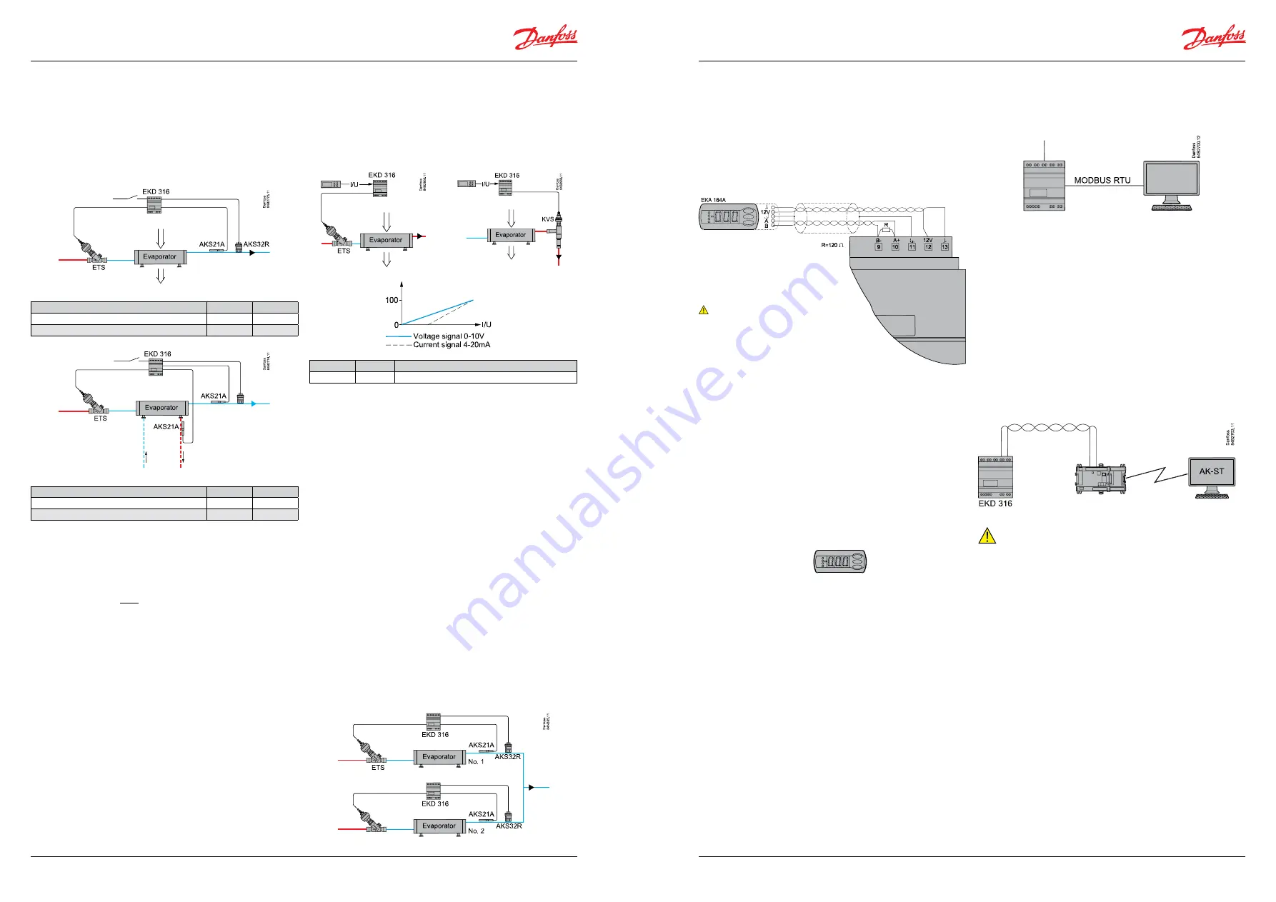
EKD 316
Danfos
s
84B3082.10
Data communication with the EKD 316 is possible using one of the
following two ways:
1. Via External display (EKA 164A)
2. Via standard MODBUS Device
Via external display (EKA 164A)
Use an external display to operate the controller. This must be
done as follows:
Note:
Max. distance between controller and
display is 30 m.
The supply voltage to the display must be
maintained at 12 V +/- 15%.
The values are shown in three digits, and with a setting you
can determine whether the temperature is shown in °C or in °F.
(Pressure in bar or psig.)
In order to change a setting, the upper and lower buttons will
give you a higher or lower value depending on the button you
are pushing. But before you change the value, you must have
access to the menu. You obtain this by pushing the upper button
for a couple of seconds – you will then enter the column with
parameter codes. Find the parameter code you want to change
and push the middle button until the value for the parameter is
shown. When you have changed the value, save the new value by
pushing once more on the middle button.
By pushing the middle button you go directly to the Main Switch
setting (r12).
Example
Set a menu
1. Push the upper button until a parameter is shown
2. Push the upper or the lower button and find the parameter you
want to change
3. Push the middle button and the value is shown
4. Push the upper or the lower button and select the new value
5. Push the middle button again to conclude the setting