DH-SMT/DK
VI.KT.F2.02
© Danfoss 06/2008
$2
!&4
Instructions
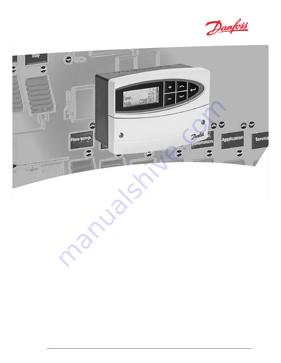
ECL Comfort 110
Application 116
Constant temperature control
of domestic hot-water systems (DHW)
User guide,
Installation & Maintenance
Page 1: ...DH SMT DK VI KT F2 02 Danfoss 06 2008 2 4 Instructions ECL Comfort 110 Application 116 Constant temperature control of domestic hot water systems DHW User guide Installation Maintenance ...
Page 2: ...override 7141 19 Min on time min activation time gear motor 7189 19 Daylight daylight saving time changeover 7198 20 ECL address master slave address 7199 20 Type 7600 21 Service 8000 22 Code no 8300 22 Ver version no 8301 22 Backlight display brightness 8310 22 Contrast display contrast 8311 22 Language 8315 23 MOD address MODBUS address 8320 23 Line Page Safety Note To avoid injury of persons an...
Page 3: ...ectrical connections 24 V a c in general 26 Connecting the temperature sensors and the ECL BUS 27 How to identify your system type 28 Adapting the ECL Comfort 110 controller 29 Manual control 30 Placing the temperature sensors 31 Checklist electrical connections 32 Frequently asked questions 33 Definitions 34 Introduction Settings overview Daily use Maintenance Installation Check ...
Page 4: ...ory setting Your setting Temp min flow temp limit min 2177 11 Temp max flow temp limit max 2178 11 Limit return temp limitation 4030 12 Gain max return temp limitation max influence 4035 13 Gain min return temp limitation min influence 4036 14 Intgr time time constant for return temp limitation 4037 14 Auto tuning 6173 15 Motor prot motor protection 6174 16 Xp proportional band 6184 16 Tn integrat...
Page 5: ...question is not connected the sensor is short circuited Select control mode During scheduled operation AUTO the symbols will show you the control mode 2 8 Change the mode AUTO COMFORT SETBACK or STANDBY Set your personal schedule It is only possible to set the personal schedules if the ECL Comfort 110 controller has a built in ECA 110 timer program Bn n A BF 2 8 This display will show the current ...
Page 6: ...ct date and time in connection with the first use of the ECL Comfort 110 controller or after a power break of more than 36 hours see the chapter on Adapting the ECL Comfort 110 controller Flow temp flow temperature control 2000 Temp min flow temp limit min 2177 Setting range Factory setting 20 110 C 10 C Set the allowed min flow temperature for your system Adjust the factory setting if required Te...
Page 7: ... the set value the controller automatically changes the desired flow temperature to obtain an acceptable return temperature The influence is set in lines 4035 and 4036 Return T limit return temp limitation 4000 Gain max return temp limitation max influence 4035 Setting range Factory setting 9 9 9 9 0 0 Determines how much the flow DHW temperature will be influenced if the return temperature is hig...
Page 8: ...ontrol Lines 6184 6185 6186 and 6187 do not need to be set when using auto tuning OFF Auto tuning is not activated ON Auto tuning is activated The auto tuning function automatically determines the control parameters for DHW control Thus you do not need to set the lines 6184 and 6185 as they are automatically set to the auto tuning function Auto tuning is typically used in connection with the insta...
Page 9: ...d using the following methods Seated valves Running time Valve stroke mm x actuator speed sec mm Example 5 0 mm x 15 sec mm 75 sec Rotating valves Running time Turning degrees x actuator speed sec degr Example 90 degr x 2 sec degr 180 sec Nz neutral zone 6187 Setting range Factory setting 1 9 K 3 K Set the acceptable flow temperature deviation Set the neutral zone to a high value if you can accept...
Page 10: ... setting 20 50 C 20 C When the desired flow temperature is above the set temperature in P1 heat T the controller automatically switches ON the circulation pump to meet the heat demand 20 50 The circulation pump is ON above the set value Application 7000 Standby T standby temperature 7093 Setting range Factory setting 5 40 C 10 C Set the desired flow temperature at standby 5 40 Desired standby flow...
Page 11: ... and signal for DHW demand from the master 1 9 The controller works as slave The slave receives information about the outdoor temperature S1 system time and signal for DHW demand from the master The slave sends information about the desired flow temperature to the master 10 14 Not used 15 The controller is master The ECL Comfort controllers can be connected via the ECL BUS to perform a larger syst...
Page 12: ... 8310 Setting range Factory setting OFF 1 30 16 The brightness of the display can be adjusted OFF No backlight 1 Weak backlight 30 Strong backlight Contrast display contrast 8311 Setting range Factory setting 0 20 10 The contrast of the display can be adjusted 0 High contrast 20 Low contrast Language 8315 Setting range Factory setting Multiple English Choose your language MOD address MODBUS addres...
Page 13: ...cut out with the dimensions 93 x 139 mm Insert the controller into the panel cut out and fix it with the clamp which is placed horisontally on the controller Establish the electrical connections Danfoss 87B789 10 For further details on mounting see the mounting guide Mounting the ECL Comfort controller Installation Optional connections for safety thermostat Terminal Description Max load 20 Supply ...
Page 14: ...elay R2 4 2 A Wire cross section 0 5 1 5 mm2 Incorrect connection can damage the TRIAC outputs Electrical connections 24 V a c in general Terminal Description Type recomm 1 and 2 Not to be used 3 and 4 S3 Flow temperature sensor ESM 11 ESMC ESMU 5 and 6 S4 Return temperature sensor ESM 11 ESMC ESMU 7 Not to be used 8 and 9 ECL BUS connections for room panel remote control ECA 60 62 ECA 61 63 10 No...
Page 15: ... storage tank with built in heating coil How to identify your system type When you switch on the controller the first time it will ask you to choose language default language is English 2 4 Choose your language Accept and go to the next menu When the language is chosen the controller will ask for date and time setting n n88 F 3 n 3 Set day dd month mm year yy hour hh and minuts mm Use the minus an...
Page 16: ... exchanger Danfoss recommends that the ESMU type to be inserted into the exchanger flow outlet Make sure that the surface of the pipe is clean and even where the sensor is mounted Return temperature sensor ESMU ESM 11 or ESMC The return sensor should always be placed in on a pipe with return water flow Room temperature sensor ESM 10 ECA 60 62 room panel or ECA 61 63 remote control Place the room s...
Page 17: ...heating cut out DHW priority etc The DHW temperature is too high during setback periods Make sure that the min flow temperature limitation is not too high See line 2177 The temperature is unstable Check that the flow temperature sensor is correctly connected and in the right place If the controller has a room temperature signal line 3000 check that the Gain is not too high Adjust the control param...
Page 18: ... compared to the max moisture content The relative humidity is measured by the ECA 62 63 Definitions Limitation temperature Temperature that influences the desired flow balance temperature Pt 1000 sensor All sensors used with the ECL Comfort controller are based on the Pt 1000 type The resistance is 1000 ohm at 0 C and it changes with approx 3 9 ohm degree Optimization The controller optimizes the...
Page 19: ...s can accept no responsibility for possible errors in catalogues brochures and other printed material Danfoss reserves the right to alter its products without notice This also applies to products already on order provided that such alterations can be made without subsequential changes being necessary in specifications already agreed All trademarks in this material are property of the respective co...