background image

DMS Manual

Power Wiring

Connect the Supply voltage to the DMS input

terminals 1/L1, 3/L2 & 5/L3.The terminals in the

Extended versions of the DMS allow two cables

to loop the power line as shown.
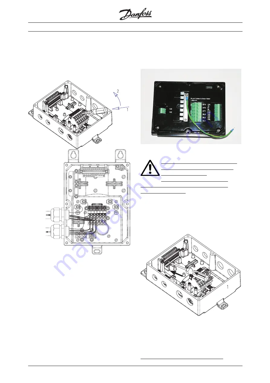
177ha011.10

Use of screw driver to open the connector clamp

3-phase Mains from

power-bus/

previous unit

3-phase Mains to

next unit

e77ha013.eps

Looping the power line - 3-phase mains

Connect the Motor terminals to the DMS output

terminals 2/T1, 4/T2 & 6/T3. Take care of the phase

sequence to have the correct direction of rotation.

The terminals in the Extended versions of the

DMS allow two cables to connect two motors

in parallel to one DMS.

Maximum cross section: 4 mm sq. (10 AWG)

For ST & SB versions, provide strain relief for power

and control cables by using the cable support

provided in the DMS unit, as shown.

Power factor correction

If a DMS is used with static power factor

correction it must be connected to the

supply side of the DMS.

Connecting power factor correction

capacitors to the output of the DMS will result

in damage to the DMS.

Control Wiring

Complete the Control wiring as shown in the

Electrical Schematic diagram.

177ha012.10

Use of a screw driver to open the connector clamp

for control terminals   [Press to open the clamp]

Rev310103

Connect Control Supply / AS-i Interface at

the terminals provided.

Contacts used for controlling these inputs should be

low voltage, low current rated (Gold flash or similar)

Maximum cross section: 2.5 mm2 (12 AWG)

Use cables complying with local regulations.

MG.05.A2.02 - VLT is a registered Danfoss trademark

6

Summary of Contents for DMS 300

Page 1: ...lutions www danfoss com drives OperatingInstructions Decentral Motor Starter DMS 300 Decentral Motor Starter DMS 300 Operating Instructions 175R0901 MG05A202 REV 2003 05 06 XREF__BC NOT LOADED ON RIP...

Page 2: ...unication 7 Earthing 7 High voltage warning 7 Galvanic isolation PELV 7 Electrical Schematic 8 Setting up DMS 9 Adjustment Settings 9 Start stop profile setting 9 Start stop profile setting table 9 Tr...

Page 3: ...ions 16 Fuses 17 Order code format 18 Special variants 19 Motor connection 19 Details of Profibus Connectivity 20 Profibus DP Slave 6 E DC 24 V 4 A DC 24 V 1A 20 Table of bits in control and status wo...

Page 4: ...ied out 2 The COASTING STOP INVERSE command applied to the DMS does not disconnect the equipment from the mains and thus is not to be used as a safety switch It is the responsibility of the user or th...

Page 5: ...Centre punch for motor mounted versions if not already mounted on a motor Wall mounting For best cooling the DMS unit should be mounted vertically If needed horizontal mounting is allowable For instal...

Page 6: ...enclosure to limit heat rise in the enclosure to maintain the internal enclosure temperature at or below 40 deg C Heat loss of DMS at rated current is 18 watts approx 40 50 60 70 80 90 100 FLC Tempera...

Page 7: ...r ST SB versions provide strain relief for power and control cables by using the cable support provided in the DMS unit as shown Power factor correction If a DMS is used with static power factor corre...

Page 8: ...cation and control cables in a separate conduit Earthing Ensure that the DMS unit is earthed properly Use the chassis earth studs provided for the purpose 4 of size M4 For type T73 units an external e...

Page 9: ...DMS Manual Electrical Schematic MG 05 A2 02 VLT is a registered Danfoss trademark 8...

Page 10: ...load current setting note 0 1Amps is always added internally 0 2A See table below Off FLC 0 1A Note Settings marked grey are applicable only in Extended versions Start stop profile setting Choose the...

Page 11: ...y calculated by the microprocessor This uses a sophisticated mathematical model to accurately reflect motor heat generation and dissipation during all stages of operation e g Starting Running Stopping...

Page 12: ...s not used FLC setting table DIP Switch bits Value Amps Example 1 for setting FLC 4 3 Amps Example 2 for setting FLC 2 9 Amps 2 B2 3 2 On Off 3 B3 1 6 Off On 4 B4 0 8 On On 5 B5 0 4 Off On 6 B6 0 2 On...

Page 13: ...t to stop NB If both Start CW Start CCW inputs are active together the motor will stop Brake Release For variants with Braking function only variants SB EB ER When a Start is initiated the DMS automat...

Page 14: ...t 0 1 No fault Fault No fault Fault No fault Fault D3 input Not used 0 1 Not used Not used Not used P0 parameter Not used P1 parameter Not used P2 parameter Not used P3 parameter Not used It is possib...

Page 15: ...e cause of the overload and let the motor cool before restarting Three 3 Motor Thermistor Trip Identify and correct the cause of motor overheating If no thermistors are connected to the DMS ensure the...

Page 16: ...romechanical Brake Supply output Electromechanical Brake Supply Output Terminals 122 123 180 VDC 1 0 A max The electromechanicalbrake supply output voltage is proportional to the mains supply voltage...

Page 17: ...frequency emissions Class B as per EN 55011 Electrostatic discharge 4 kV contact and 8 kV air discharge no effect on operation Radio frequency electromagnetic field 0 15 MHz to 1 0 GHz no effect on op...

Page 18: ...25A 415 VAC or equivalent HRC fuses Semiconductor fuses are required to meet UL C UL Certification Semiconductor fuses listed below are manufactured by Bussmann and should be ordered directly from Bus...

Page 19: ...DMS Manual Order code format MG 05 A2 02 VLT is a registered Danfoss trademark 18...

Page 20: ...10 Motor thermistor B 4 Electromechanical brake A PE Earth connection 5 Electromechanical brake B Example 2 Variant T22 or T62 DMS Extended unit with an integrated service switch The service switch c...

Page 21: ...x 2 5sq mm 203 DC 0 V 204 DC 24 V galvanic isolation isolation voltage DC 500 V between bus and electronics DC 2 5kV between module supply and inputs outputs Bus interface Bus system Profibus DP modul...

Page 22: ...0 1 1 1 1 x x x x x 1 0 1 1 1 x x x x x 2 1 0 1 1 x x x x x 3 0 0 1 1 x x x x x 4 1 1 0 1 x x x x x 5 0 1 0 1 x x x x x 6 1 0 0 1 x x x x x 7 0 0 0 1 x x x x x 8 1 1 1 0 x x x x x 9 0 1 1 0 x x x x 0...

Page 23: ...5 H Han 10E connector 19 High voltage warning 7 M Motor mounting 4 Motor thermistors 7 O Operation 12 Operation with AS i Interface 12 Order code format 18 P Power factor correction 6 Power Wiring 6 P...

Page 24: ...lutions www danfoss com drives OperatingInstructions Decentral Motor Starter DMS 300 Decentral Motor Starter DMS 300 Operating Instructions 175R0901 MG05A202 REV 2003 05 06 XREF__BC NOT LOADED ON RIP...

Reviews: