


Installation manual for DM700 ECDIS
Copyright Danelec Marine A/S
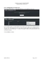
MAN11805-10
Page 8/67
2.1 Main Unit
The main unit must be installed on a table top or inside a console using the mounting foot or
mounting ‘angle and plate’.
Consult
Appendix A - Installation drawings for main
for details
The main unit contains the following parts:
2.1.1 DPU
The data processing unit contains the computer for the ECDIS software and communication I/O
interfaces.
Indicator LED’s and other features are described in
MAN11804 “User manual for DM700 ECDIS
hardware”
.
DPU front panel
DPU Back panel
2.1.2 USB hardware key
The USB hardware key contains the keys needed for enabling access to charts.
The USB hardware key is located under the service cover, on the DM700 ECDIS DPU.
2.2 Monitor
The monitor must be installed on a table top using the monitor hinge, or be flush mounted in the
console. Consult the installation manual supplied with the monitor.
2.2.1 Monitor HMI
A buzzer
Power button for setting the computer for the ECDIS software in standby and starting it up
again.
The monitor HMI must be installed on the monitor hinge or if the monitor is panel mounted
adjacent to the monitor.
Summary of Contents for DM700 ECDIS
Page 61: ...Installation manual for DM700 ECDIS Copyright Danelec Marine A S MAN11805 10 Page 61 67...
Page 63: ...Installation manual for DM700 ECDIS Copyright Danelec Marine A S MAN11805 10 Page 63 67...
Page 65: ...Installation manual for DM700 ECDIS Copyright Danelec Marine A S MAN11805 10 Page 65 67...
Page 66: ...Installation manual for DM700 ECDIS Copyright Danelec Marine A S MAN11805 10 Page 66 67...
Page 67: ...Installation manual for DM700 ECDIS Copyright Danelec Marine A S MAN11805 10 Page 67 67...


