


Standalone MMC Hardware Manual
83
Danaher Motion
version 15.1
Standalone MMC Control
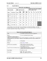
4.6.2.5
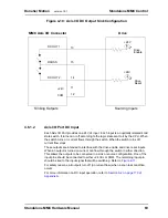
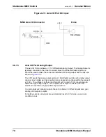
Aux I/O Port Analog Input
The Aux I/O Port provides one differential analog input channel. The input range is
±10 VDC. The analog input voltage is sampled every 100 µsec by a 12-bit A/D
converter. The most recent conversion result is stored in an on-board register. This
register can be read at any time by the application.
The analog input signal passes through a common mode and differential mode filter
prior to being applied to the A/D converter. These filters improve the noise immunity of
the module.
4.7
SERCOS Motion Control Connections & Operation
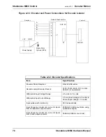
This section provides information on connecting to the SERCOS Motion Control
board, which is located on the left side of a SERCOS MMC Control.
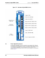
The MMC SERCOS board is an alternate type of motion control used as part of an
MMC base unit. It provides an interface between the MMC and 1 fiber optic ring
(MMC-S8) or 2 fiber optic rings (MMC-S16). A ring can have from one to eight
SERCOS slaves. The module contains an on board processor. The MMC-S8 has one
SERCOS ring port located at the center of the module. The MMC-S16 has an
additional ring port located at the top of the module. Each ring port has a receive and
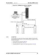
a transmit fiber optic connector. There is also an RS232 port used for loading FLASH
memory updates.
The SERCOS board is controlled by an application created in PiCPro. An on-board
processor interprets the functions and performs appropriate operations according to
the SERCOS communications protocol.
Data Transfer Rates of 2 Mbaud, 4 Mbaud, 8 Mbaud, and 16 Mbaud are available,
and Update Rates of 1 msec, 2 msec, 4 msec, and 8 msec are available.
If a scan loss occurs, SERCOS communications are reset. There is no
communication with the SERCOS slaves until they are re-initialized.
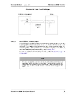
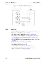
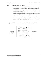
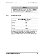
4.7.1
SERCOS Receive and Transmit Ports
The SERCOS Receive Port and Transmit Port connectors (labeled “RECV1” and
“XMIT1” on the front of the Module) located at the center of the module can connect to
one SERCOS ring. On an MMC-S16, there is a second Receive Port connector and a
second Transmit Port connector (labeled “RECV2” and “XMIT2” on the front of the
Module) located at the top of the module that can connect to another SERCOS ring.
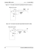
The connection to each ring is made through a pair of female fiber optic SMA
connectors. The module’s transmitter is connected to the first receiver in the loop and
the module’s receiver is connected to the last transmitter in the loop.
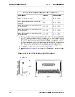
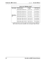
Available SERCOS cables are shown in
Summary of Contents for Standalone MMC
Page 4: ......
Page 8: ...8 Standalone MMC Hardware Manual Table of Contents version 15 1 Danaher Motion ...
Page 94: ...94 Standalone MMC Hardware Manual Standalone MMC Control version 15 1 Danaher Motion ...
Page 169: ...Standalone MMC Hardware Manual 169 Danaher Motion version 15 1 CE and EMC Guidelines ...
Page 170: ...170 Standalone MMC Hardware Manual CE and EMC Guidelines version 15 1 Danaher Motion ...
Page 171: ...Standalone MMC Hardware Manual 171 Danaher Motion version 15 1 CE and EMC Guidelines ...
Page 172: ...172 Standalone MMC Hardware Manual CE and EMC Guidelines version 15 1 Danaher Motion ...


