


134
Standalone MMC Hardware Manual
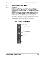
MMC DeviceNet
TM
Option Module
version 15.1
Danaher Motion
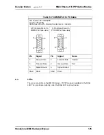
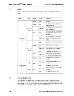
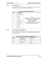
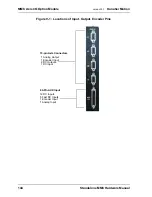
7.3
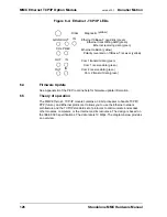
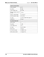
LEDs
The two configuration port LEDs and the two DeviceNet port LEDs are described
below.
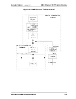
7.4
Theory of Operation
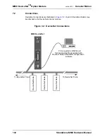
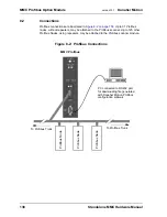
The DeviceNet scanner module provides a memory image of the nodes (slaves)
connected to a DeviceNet network. It is this memory image that is controlled by your
LDO created in PiCPro. The module’s on-board processor continually transfers data
between this memory image and the actual DeviceNet nodes.
Port
LED
Color
State
Definition
DeviceNet
Port
Network
status
None
OFF
Off-line
Green
ON
On-line and connected to at
least one node
Flashing
On-line but connection nodes
not established
Red
ON
Unrecoverable Fault (duplicate
MAC ID check failed, critical
bus fault etc.)
Flashing
I/O connections in timed-out
state or other Recoverable
Fault
Scanner
status
Green
OFF
No power or else reset assert-
ed
ON
Scanner OK and active
Flashing
Scanner OK but not active
Red
ON
Hardware or software error
Flashing
Recoverable configuration er-
ror (invalid data downloaded)
Orange
ON
Configuration (download)
mode
Configuration
Port
IN
Red
Flickering
Data is being passed to the
module
OFF
No data to the module
OUT
Red
Flickering
Data is being passed from the
module
OFF
No data from the module
Summary of Contents for Standalone MMC
Page 4: ......
Page 8: ...8 Standalone MMC Hardware Manual Table of Contents version 15 1 Danaher Motion ...
Page 94: ...94 Standalone MMC Hardware Manual Standalone MMC Control version 15 1 Danaher Motion ...
Page 169: ...Standalone MMC Hardware Manual 169 Danaher Motion version 15 1 CE and EMC Guidelines ...
Page 170: ...170 Standalone MMC Hardware Manual CE and EMC Guidelines version 15 1 Danaher Motion ...
Page 171: ...Standalone MMC Hardware Manual 171 Danaher Motion version 15 1 CE and EMC Guidelines ...
Page 172: ...172 Standalone MMC Hardware Manual CE and EMC Guidelines version 15 1 Danaher Motion ...


