


Danaher Motion
05/2008
Connector Pinout and DEscriptions
S200-CNS Product Manual
31
8
CONNECTOR PINOUT AND DESCRIPTIONS
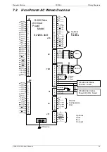
The following section describes the user connections to the S200 Position Node by connector. The
front part of this section presents AC / DC input Power and Power Terminal wirings for various drive
models. J1 and TB1 vary according to the model. Please refer to the proper description for your
model.
8.1 PE
A
LL
D
RIVE
M
ODELS
Each S200 Position Node product has at least one screw terminal from its frame exposed to the
front of the product for customer wiring to Protective Earth (PE) ground. This connection should be
made with heavy gage, high strand count wire and a ring lug terminal directly back to the incoming
earth ground distribution block. Power should not be applied if this connection does not exist.
PE Ground Terminals
(Typical)