


Connector Pinout and DEscriptions
05/2008
Danaher Motion
34
S200-CNS Product Manual
8.3 J1
–
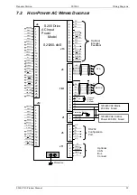
AC
I
NPUT
C
ONTROL
P
OWER
H
IGH
P
OWER
AC
M
ODELS
Models: S21260-xNS
Please refer to the Specifications section for fusing and rating information.
NOTE
It is the customer’s responsibility to supply appropriate fuses or circuit
breakers in the J1 AC drive power lines to comply with local electrical
codes.
NOTE
For maximum line droop tolerance connect logic power to 230Vac instead of
115Vac
CAUTION
To avoid damage to the connector and drive, NEVER plug or unplug J1 with
power applied.
Mating Connector Information:
Screw Terminal Connector
12 – 24 AWG Wire Range, Phoenix MSTB2,5/3-STF-5,08-BK
OR
Spring Cage Clamp Connector
12 – 24 AWG Wire Range, Phoenix FKC 2,5/3-SFT-5,08-BK
OR
Crimp Connector
Crimp Shell: 14-20 AWG Wire Range, Phoenix MSTBC 2,5/3-STZF-5,08-BK
Crimp Contact: 14-16 AWG Wire Range, Phoenix MSTBC-MT 1,5-2,5
Crimp Contact: 18-20 AWG Wire Range, Phoenix MSTBC-MT 0,5-1,0
Refer to
.
Pin
Description
J1-1
E (Protective Earth) – Must be tied back to central earth bar.
J1-2 C2 CTRL VAC – Logic control Power. Use 120 or 240Vac.
J1-3 C1 CTRL VAC – Logic Control Power. Use 120 or 240 Vac.
PE C2 C1