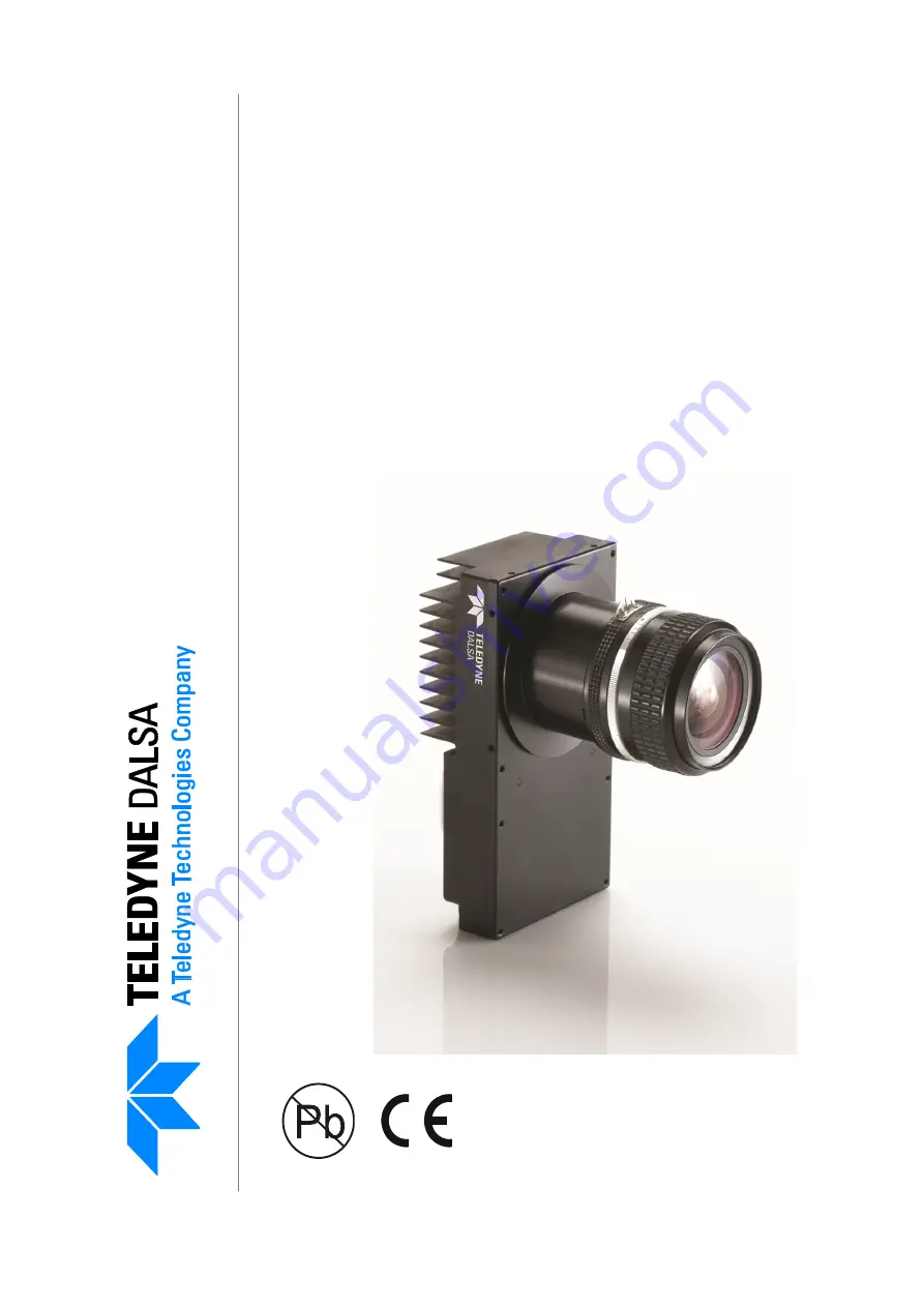
Piranha 3
Camera User’s Manual
P3-80-12k40-00-R
P3-80-08k40-00-R
P3-87-12k40-00-R
P3-87-08k40-00-R
8k to 12
k Lin
e S
can CC
D Ca
meras
7-Jun-11
03-032-10216-06
www.teledynedalsa.com
All manuals and user guides at all-guides.com
all-guides.com
Page 1: ...Manual P3 80 12k40 00 R P3 80 08k40 00 R P3 87 12k40 00 R P3 87 08k40 00 R 8k to 12k Line Scan CCD Cameras 7 Jun 11 03 032 10216 06 www teledynedalsa com All manuals and user guides at all guides com...
Page 2: ...ximately 1 000 employees worldwide headquartered in Waterloo Ontario Canada Established in 1980 the company designs develops manufactures and markets digital imaging products and solutions in addition...
Page 3: ...ED 15 Camera Link Configuration 18 Input Signals Camera Link 19 Output Signals Camera Link 19 2 3 Camera Link Video Timing 20 Software Interface How to Control the Camera _____________________________...
Page 4: ...Light Sources 65 Filters 65 Lens Modeling 65 Magnification and Resolution 66 Troubleshooting________________________________________________________ 67 5 1 Common Solutions 67 5 2 Troubleshooting Usin...
Page 5: ..._ 75 B1 Error Handling 75 B2 All Available Commands 76 EMC Declaration of Conformity _____________________________________________ 85 Revision History _________________________________________________...
Page 6: ...Piranha 3 User Manual 03 032 10216 06 Teledyne DALSA 6 All manuals and user guides at all guides com a l l g u i d e s c o m...
Page 7: ...tic tap balancing algorithms RoHS CE and FCC compliant Key Specifications Value Units 8k 12k Typ 0dB Gain Typ 0dB Gain Pixel Pitch m 7 x 7 5 x 5 Camera Size mm 150 H x 42 L x 80 W P3 80 mm 85 H x 54 2...
Page 8: ...ount of time than ever before Applications The Piranha 3 family is ideal for applications requiring high speed superior image quality and high responsivity Applications include Flat panel display insp...
Page 9: ...05 0 25 0 4 0 05 0 05 0 25 0 4 Lens Mount M72x0 75 M72x0 75 Mechanical Interface Units Notes Camera Size mm h x l x w 150 x 42 x 80 P3 80 85 x 54 2 x 80 P3 87 Mass g 630 P3 80 125 P3 87 Connectors po...
Page 10: ...8 4 8 10 16 4 PRNU ECD DN 120 330 120 330 140 330 2 PRNU ECE DN 125 330 140 330 220 330 2 PRNU Pixel to Pixel DN 80 255 80 255 80 255 PRNU Corrected ECD ECE DN DN 16 16 48 48 18 18 64 64 48 80 80 232...
Page 11: ...lor temperature with 750nm cutoff filter light source 59 W cm 2 12k camera and 71 3 W cm 2 8k camera light intensity line rate 2500 Hz 12k camera and 5000 Hz 8k camera ECD 25 C ambient temperature 2 E...
Page 12: ...l Reset and Shift RegisterStructures Storage Well with Exposure Control Reset and Shift RegisterStructures Table 3 12k40 Pixel Readout Tap First Pixel 1 1 3071 odd pixels 2 2 3072 even pixels 3 3073 6...
Page 13: ...Piranha 3 User Manual Teledyne DALSA 03 032 10216 06 13 7 8191 6141 odd pixels 8 8192 6142 even pixels 1 4 Responsivity Figure 2 Responsivity Graphs All manuals and user guides at all guides com...
Page 14: ...Piranha 3 User Manual 03 032 10216 06 Teledyne DALSA 14 All manuals and user guides at all guides com...
Page 15: ...ables or connectors or the camera may be damaged 6 Connect Camera Link and power cables 7 After connecting cables apply power to the camera 8 Check the diagnostic LED See 2 2 1 LED Status Indicator fo...
Page 16: ...and the corresponding LED states When more than one condition is active the LED indicates the condition with the highest priority Error and warning states are accompanied by corresponding messages fu...
Page 17: ...o prevent LVDS common mode range violation Note Performance specifications are not guaranteed if your power supply does not meet the 12V to 15V requirements WARNING It is extremely important that you...
Page 18: ...details on setting the Camera Link configuration Table 7 Camera Link Hardware Configuration Summary Configuration 8 Bit Ports Supported Serializer Bit Width Number of Chips Number of MDR26 Connectors...
Page 19: ...dge of EXSYNC to trigger line readout Section 3 2 1 Exposure Mode Line Rate and Exposure Time details how to set frame times exposure times and camera modes Output Signals Camera Link These signals in...
Page 20: ...imum low width of the EXSYNC pulse when not in SMART EXSYNC mode 100 twSYNC SMART The minimum low width of the EXSYNC pulse when in SMART EXSYNC modes to guarantee the photosites are reset 3 000 twSYN...
Page 21: ...imes the readout clock period Pretrigger 0 38 400 12k 25 600 8k tOVERHEAD Is the number of pixels that must elapse after the falling edge of LVAL before the EXSYNC signal can be asserted This time is...
Page 22: ...Piranha 3 User Manual 03 032 10216 06 Teledyne DALSA 22 All manuals and user guides at all guides com...
Page 23: ...ce uses a simple ASCII based protocol and the camera does not require any custom software Serial Protocol Defaults 8 data bits 1 stop bit No parity No flow control 9 6kbps Camera does not echo charact...
Page 24: ...nds and parameters through the serial interface There are two different help screens available One lists all of the available commands to configure camera operation The other help screen lists all of...
Page 25: ...0 4 rc reset camera rfs restore factory settings roi region of interest xyxy 1 12288 1 1 1 12288 1 1 rpc reset pixel coeffs rus restore user settings sag set analog gain tf 0 8 10 0 10 0 sao set anal...
Page 26: ...sag ccg ugr sao cao ccf sdo ccp ssb ssg Camera Link Mode Camera Throughput Set Upper Threshold Set Lower Threshold clm sot sut slt Generate a Test Pattern End of Line Sequence Set Pretrigger svm els s...
Page 27: ...ate generation Syntax sem i Syntax Elements i Exposure mode to use Factory setting is 7 Notes Refer to Table 11 Piranha 3 Exposure Modes for a quick list of available modes or to the following section...
Page 28: ...s entered When setting the exposure time using the set command line time will be increased if necessary to accommodate the exposure time Under this condition the line time will equal the exposure time...
Page 29: ...Line Rate EXSYNC and External Pixel Reset PRIN In this mode the falling edge of EXSYNC sets the line period and the rising edge of PRIN sets the start of exposure time Figure 9 EXSYNC controls Line Pe...
Page 30: ...t Setting the Line Rate Purpose Sets the camera s line rate in Hz Camera must be operating in exposure mode 2 or 7 Syntax ssf f Syntax Elements i Desired line rate in Hz Allowable values are 12k 2500...
Page 31: ...Output Format 3 3 1 Setting the Camera Link Mode Purpose Sets the camera s Camera Link configuration number of Camera Link taps and data bit depth Refer to Table 12 for a description of each Camera L...
Page 32: ...tap 3 4 3 CCD tap 5 6 4 CCD tap 7 8 Note Concatenated taps are interleaved Refer to section 1 3 for a sensor readout description 80MHz 12 clm 21 Full 8 Camera Link taps where 1 CCD tap 1 2 CCD tap 2...
Page 33: ...t the region of interest a few pixels inside the actual useable image Syntax roi x1 y1 x2 y2 Syntax Elements x1 Pixel start number Must be less than the pixel end number in a range from 1 to sensor re...
Page 34: ...or example in a low light situation the brightest part of the image may be consistently coming in at only 50 of the DN An analog gain of 6 dB 2x will ensure full use of the dynamic range of the A D co...
Page 35: ...This camera has the ability to calculate correction coefficients in order to remove non uniformity in the image This video correction operates on a pixel by pixel basis and implements a two point cor...
Page 36: ...t camera performance and calibration results For best results the analog gain should be adjusted for the expected operating conditions and the ratio of the brightest to darkest pixel in a tap should b...
Page 37: ...ld see close to zero output gl gla sao cao 0 sag ccf wfc wus epc 1 0 i 1 Place a white reference in front of the camera 2 Verify that the output signal level is within range by issuing the command or...
Page 38: ...end the following commands sdo 0 0 epc 0 0 ssb 0 0 ssg 0 4096 Setting Analog Gain Purpose Sets the camera s analog gain value Analog gain is multiplied by the analog signal to increase the signal stre...
Page 39: ...ed target 4 This algorithm adjusts the analog gain so that the maximum pixel per tap within the ROI of the multi line average css command is equal to the specified target t Tap value Use 0 for all tap...
Page 40: ...mmand gcp or get sao Example sao 3 35 Related Commands cao Calibrating Analog Offset Purpose Instead of manually setting the analog offset to a specific value the camera can determine appropriate offs...
Page 41: ...taps remain unchanged Figure 14 Calibrating Analog Gain for a Tap outside of the Region of Interest Tap 1 odd Tap 2 even Video Region of Interest ccg 1 4 2800 Since tap 4 is within the region of inter...
Page 42: ...Figure 15 Calibrating Analog Gain for a Tap inside the Region of Interest ccg 1 2 2800 Since tap 2 is completely outside the region of interest an error message is returned and analog gain calibation...
Page 43: ...en calibrating all taps taps completely outside the region of interest in this example interleaved taps 1and 2 are calibrated to the average analog gain of taps within the region of interest Taps with...
Page 44: ...nd digital adjustments before performing FPN correction Perform FPN correction before PRNU correction Refer to Calibrating the Camera to Remove Non Uniformity Flat Field Correction on page 35 for a pr...
Page 45: ...and Related Commands ssg Example sdo 0 100 PRNU Correction Performing PRNU Correction to a Camera Calculated Value Purpose Performs PRNU correction and eliminates the difference in responsivity betwee...
Page 46: ...performs the same function as the cpp command but requires that you enter a target value 3 This algorithm includes an analog gain adjustment prior to PRNU calibration Analog gain is first adjusted so...
Page 47: ...f the range x Coefficient value in a range from 0 to 28671 where Notes The first pixel of the range must be less than the last Example spr 4001 4096 0 Subtracting Background Purpose Use the background...
Page 48: ...put swing after a background subtract When subtracting a digital value from the digital video signal using the ssb command the output can no longer reach its maximum Use this command to correct for th...
Page 49: ...ll the current pixel coefficients in the order FPN PRNU FPN PRNU The camera also returns the pixel number with each coefficient Example dpc 10 20 Returning FPN Coefficients Purpose Returns a pixel s F...
Page 50: ...calculations including line counter line sum pixels above threshold pixels below threshold and derivative line sum within the region of interest These basic calculations are used to calibrate analog...
Page 51: ...e these values to focus the camera Generally the greater the sum the greater the image contrast and better the focus 14 Differential line sum 15 8 15 Differential line sum 23 16 16 Differential line s...
Page 52: ...efficients are stored separately from other data To save all current user settings to EEPROM use the command wus The camera will automatically restore the saved user settings when powered up Note Whil...
Page 53: ...ts A factory calibrated set of coefficients is available Syntax lpc i Syntax Elements i FPN coefficients set to save 0 Factory calibrated pixel coefficients 1 Coefficient set one 2 Coefficient set two...
Page 54: ...to read video data This functionality can be used to verify camera operation and to perform basic testing without having to connect the camera to a frame grabber This information is also used for col...
Page 55: ...Lines of Video Purpose Returns the average for multiple lines of video data without pixel coefficients or test pattern The number of lines to sample is set and adjusted by the css command The camera...
Page 56: ...erature problem or the camera will shutdown again The camera allows you to send the vt verify temperature command while it is in this state 3 6 4 Voltage Measurement The command vv displays the camera...
Page 57: ...rmware FPGA Design Rev xxx xx DSP design revision number UART Baud Rate 9600 Serial communication connection speed set with the sbr command See Setting Baud Rate on page 24 for details Exposure Mode 2...
Page 58: ...o section 3 4 2 Analog and Digital Signal Processing Chain for details PRNU Coefficients off States whether PRNU coefficients are on or off Set with the epc command Refer to section 3 4 2 Analog and D...
Page 59: ...Gain dB 6 0 6 0 6 0 6 0 This is the sum of the analog gain and analog gain reference values and is the total analog gain being used by the camera Analog Offset 100 100 100 100 100 100 100 100 Analog...
Page 60: ...er get clm Returns the current Camera Link mode get css Returns the number of line samples averaged for pixel coefficient calculations or for output of gla command get els Returns whether the end of l...
Page 61: ...exposure time 7 Internal programmable SYNC maximum exposure time Factory setting get sfc x Returns the FPN coefficient for the pixel number idicated x pixel number within the range 1 to sensor pixel c...
Page 62: ...get wfc Returns whether FPN coefficients have been saved 0 No FPN coefficients saved 1 Pixel coefficients have been saved get wpc Returns whether PRNU coefficients have been saved 0 No PRNU coefficien...
Page 63: ...iranha 3 User Manual Teledyne DALSA 03 032 10216 06 63 4 Optical and Mechanical Considerations 4 1 Mechanical Interface Figure 18 P3 80 Mechanical Drawing All manuals and user guides at all guides com...
Page 64: ...5 2x 49 5 15 0 2x 55 0 2x 6 0 4x 55 0 12 5 6 0 2x 72 5 49 9 69 4 14 1 6 56 0 25 CCD imaging distance from top of CCD to datum A 54 2 29 8 2x 38 7 60 1 M3x0 5 x 6 0 deep 4x M3x0 5 x 6 0 deep 2x M3x0 5...
Page 65: ...enerally provide very little blue relative to IR Fiber optic light distribution systems generally transmit very little blue relative to IR Some light sources age over their life span they produce less...
Page 66: ...t resolution size By similar triangles the magnification is alternatively given by m f OD These equations can be combined to give their most useful form h h f OD This is the governing equation for man...
Page 67: ...eral and specific solutions listed in sections 5 1 5 2 and 5 3 2 If these solutions do not resolve your problem see section 5 4 on getting product support 5 1 Common Solutions Connections The first st...
Page 68: ...the proper timing and connections between the camera and the frame grabber and verify the proper output along the digital processing chain Verify Voltage To check the camera s input voltages use the...
Page 69: ...ntire pad with solvent 6 Wipe across the length of the window in one direction with the moistened end first followed by the rest of the pad The dry part of the pad should follow the moistened end The...
Page 70: ...Piranha 3 User Manual 03 032 10216 06 Teledyne DALSA 70 All manuals and user guides at all guides com...
Page 71: ...ra Link Implementation Road Map available from the link details how we standardize the use of the Camera Link interface LVDS Technical Description Low Voltage Differential Signaling LVDS is a high spe...
Page 72: ...ct The signals are Camera Control 1 CC1 Camera Control 2 CC2 Camera Control 3 CC3 Camera Control 4 CC4 The Piranha 3 uses the following camera control signals Table 15 Camera Control Configuration C1...
Page 73: ...ial Camera Link specification available from the Web site here Power Power will not be provided on the Camera Link connector The camera will receive power through a separate cable Camera manufacturers...
Page 74: ...Piranha 3 User Manual 03 032 10216 06 Teledyne DALSA 74 All manuals and user guides at all guides com...
Page 75: ...meter was clipped to the current operating range Use GCP to see value used Warning 05 Missing codes insufficient digital gain Output when the digital gain is such that missing codes are to be expected...
Page 76: ...ure exceeds the specified operating range Indicates that the camera has shut itself down to prevent damage from further overheating B2 All Available Commands As a quick reference the following table l...
Page 77: ...d target 4 This algorithm adjusts the analog gain so that all tap ROI pixels are within 98 of the specified target value and then performs a PRNU correction t Tap value Use 0 for all taps or 1 to 8 fo...
Page 78: ...libration Analog gain is first adjusted so that the peak pixel value in tap s ROI is within 97 to 99 of the specified target value It then calculates the PRNU coefficients using the target value as sh...
Page 79: ...Pixel Coefficients on page 49 for details get camera model gcm Reads the camera model number get camera parameters gcp Reads all of the camera parameters get camera serial gcs Read the camera serial...
Page 80: ...s lpc i Loads the previously saved pixel coefficients from non volatile memory where i is 0 Factory calibrated coefficients 1 Coefficient set one 2 Coefficient set two 3 Coefficient set three 4 Coeffi...
Page 81: ...l communication port Baud rates 9600 19200 57600 and 115200 Default 9600 Refer to section Setting Baud Rate on page 24 for details set digital offset sdo t i Subtracts the input value from the video s...
Page 82: ...This command works in conjunction with the clm command and determines the pixel rate of the camera 320 4 taps at 80MHz or 8 taps at 40MHz This command is currently not configurable in the Piranha 3 c...
Page 83: ...ormal video mode and test patterns 0 Normal video mode 1 12 bit ramp test pattern 2 8 bit step test pattern Refer to section 3 6 1 Generating a Test Pattern for details update gain reference ugr Chang...
Page 84: ...6 06 Teledyne DALSA 84 Command Syntax Parameters Description write user settings wus Write all of the user settings to EEROM Refer to section 3 5 Saving and Restoring Settings for details All manuals...
Page 85: ...61000 3 3 2001 EN 61326 2001 IEC 61326 2002 IEC EN 61000 4 2 2001 IEC EN 61000 4 3 2002 ENV 50204 IEC EN 61000 4 4 2004 IEC EN 61000 4 5 2001 IEC EN 61000 4 6 2004 IEC EN 61000 4 11 2004 FCC PART 15 S...
Page 86: ...Piranha 3 User Manual 03 032 10216 06 Teledyne DALSA 86 This Declaration corresponds to EN 45 014 All manuals and user guides at all guides com a l l g u i d e s c o m...
Page 87: ...DC and Control Data 1 Revised allowable line rate values page 30 12k 2500 23619Hz and 8k 2500 33855Hz Reference to the camera with square body and heat sink P3 87 12k40 01 00 R removed 04 Camera model...
Page 88: ...Piranha 3 User Manual 03 032 10216 06 Teledyne DALSA 88 All manuals and user guides at all guides com...
Page 89: ...ing 50 loading 50 resetting 50 command format 23 list 76 parameters 24 commands categories 26 connectors 15 19 Camera Link 18 Hirose 17 power 17 D dark calibration See flat field correction dark patch...
Page 90: ...e dropout 68 line rate 9 setting 30 line rate 27 line statistics 54 LVAL 72 LVDS 71 pairs 72 M magnification 66 MDR26 See Camera Link connector mechanical drawing 63 specifications 9 models 8 modes de...
Page 91: ...pecifications electrical 9 key 7 mechanical 9 optical 9 performance 9 sensor 9 statistics 54 status camera LED 16 subtracting background 47 sync frequency 56 T tap matching 39 temperature measurement...