22
•
Linea HS Multifield Camera
Setting Up for Imaging
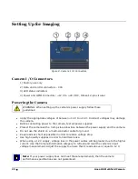
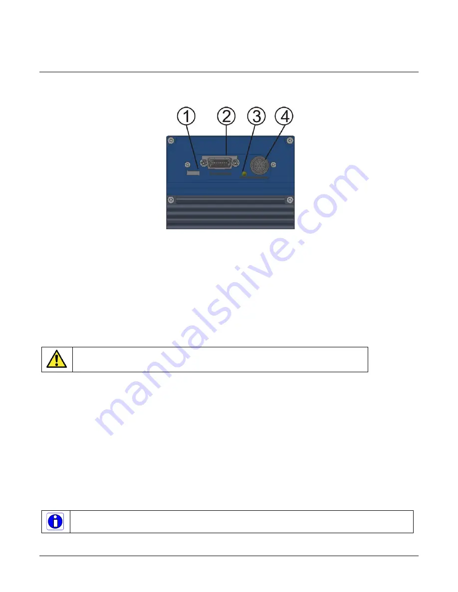
Figure 8. Camera I / O Connectors
Camera I / O Connectors
1) Factory use only
2) Data and control connectors - CX4
3) LED status indicators
4) Power and GPIO connectors: +12 V to +24 V DC, Hirose 12-pin circular
Powering the Camera
WARNING: When setting up the camera’s power supply follow these
guidelines:
•
Apply the appropriate voltages of b12 V to +24 V. Incorrect voltages may damage
the camera.
•
Before connecting power to the camera, test all power supplies.
•
Protect the camera with a 3 amp slow-blow fuse between the power supply and the camera.
•
Do not use the shield on a multi-conductor cable for ground.
•
Keep leads as short as possible in order to reduce voltage drop.
•
Use high quality supplies in order to minimize noise.
•
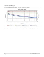
When using a 12 V supply, voltage loss in the power cables will be greater due to the higher
current. Use the Camera Information category to refresh and read the camera’s input
voltage measurement. Adjust the supply to ensure that it reads above or equal to 12 V.
Note: If your power supply does not meet these requirements, then the camera
performance specifications are not guaranteed.

