background image


110  

  Additional Reference Information 

Linea SWIR GigE Series Camera 

Lens Modeling 

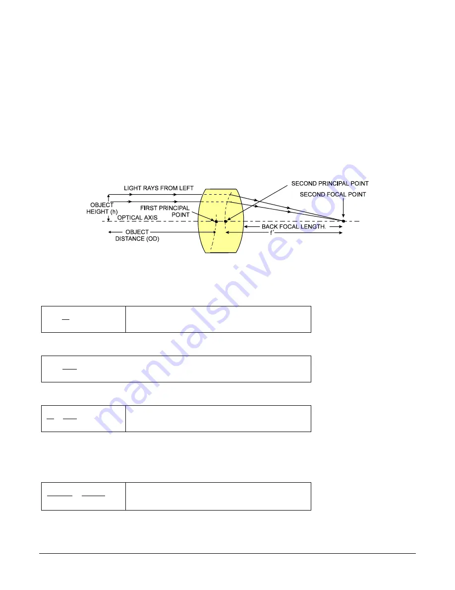
A lens surrounded by air may be modeled for camera purposes using three primary points: first 

and second principal points and the second focal point. The primary points for a lens should be 

available from the data sheet or manufacturer. Primed quantities denote characteristics of the 

image side of the lens, h is the object height and h

 is the image height. 

The focal point is the point at which the image of an infinitely distant object is brought to focus. 

The effective focal length (f

) is the distance from the second principal point to the second focal 

point. The back focal length (BFL) is the distance from the image side of the lens surface to the 

second focal point. The object distance (OD) is the distance from the first principal point to the 

object. 

Primary Points in a Lens System 


Figure 67: Lens System Diagram 

Magnification and Resolution 

The magnification of a lens is the ratio of the image size to the object size: 

h

h

m

'

=


Where m is the magnification, h’ is the image height (pixel 

size) and h is the object height (desired object resolution 

size). 

 
By similar triangles, the magnification is alternatively given by: 

OD

f

m

'

=


These equations can be combined to give their most useful form:  

OD

f

h

h

'

'

=


This is the governing equation for many object and image 

plane parameters. 


Example:

 An acquisition system has a 512 x 512-element 10 um pixel pitch, a lens with an effective 

focal length of 45 mm and requires that 100 

m

m in the object space correspond to each pixel in the 

image sensor. Using the preceding equation, the object distance must be 450 mm (0.450m). 


OD

mm

m

m

45

100

10

=

m

m


)

450

.

0

(

450

m

mm

OD

=


Summary of Contents for Linea SWIR GigE 1K

Page 1: ...Linea SWIR GigE Camera User s Manual InGaAs Line Scan Camera sensors cameras frame grabbers processors software vision solutions June 12 2020 P N 03 032 20280 02 www teledynedalsa com ...

Page 2: ...a business unit of Teledyne Digital Imaging Inc is an international high performance semiconductor and Electronics Company that designs develops manufactures and markets digital imaging products and solutions in addition to providing wafer foundry services Teledyne DALSA offers the widest range of machine vision components in the world From industry leading image sensors through powerful and sophi...

Page 3: ...SWIR GIGE WITH THE SAPERA API 19 NETWORK AND COMPUTER OVERVIEW 19 INSTALLATION 20 Procedure 20 Camera Firmware Updates 20 GigE Server Verification 20 GigE Server Status 21 OPTIMIZING THE NETWORK ADAPTER USED WITH LINEA SWIR GIGE 21 Running the Network Configuration Tool 22 QUICK STARTUP WITH CAMEXPERT 23 About the User Defined Camera Name 24 OPERATIONAL REFERENCE 25 USING CAMEXPERT WITH LINEA SWIR...

Page 4: ...ra Flat Field Coefficients File 57 Important Factors about Flat Field Processing 57 How to do a FFC Setup 57 Set up Black and Bright Acquisitions with the Histogram Tool 58 Flat Field Correction Calibration 60 Line Profile Example 61 FPN Correction 62 PRNU Correction 64 CYCLING PRESET MODE CONTROL CATEGORY 66 Cycling Preset Mode Control Feature Description 67 Using Cycling Presets 69 Initial Examp...

Page 5: ...ers 100 External Inputs Using Common Emitter NPN Driver 100 External Inputs Using a Balanced Driver 101 Output Signals Electrical Specifications 101 External Output Details and DC Characteristics 101 External Output AC Timing Characteristics 102 External Outputs Using External TTL LVTTL Drivers 103 External Outputs Using External LED Indicators 103 COMPUTER REQUIREMENTS FOR LINEA SWIR GIGE CAMERAS...

Page 6: ...6 Before Contacting Technical Support 126 Camera Fails to Establish Connection with Host PC 126 INSTALLATION ISSUES AND FUNCTIONAL PROBLEMS 130 Device Available with Operational Issues 130 Firmware Updates 130 Power Failure During a Firmware Update Now What 130 Cabling and Communication Issues 131 Power supply problems 131 Communication Problems 131 Acquisition Error without Timeout Messages 132 N...

Page 7: ... EVENT 49 Figure 25 CounterStartSource Signal 50 Figure 26 CounterStartSource Line 50 Figure 27 Advanced Processing Features 51 Figure 28 Black Acquisition Histogram 58 Figure 29 Bright Acquisition Histogram 59 Figure 30 Advanced Processing Features 60 Figure 31 Set Correction Mode Off 61 Figure 32 Bare Image Line Profile of a White Uniform Object 61 Figure 33 Sensor Control category 62 Figure 34 ...

Page 8: ...Conformity 107 Figure 66 Lens Image Circle Illustration 108 Figure 67 Lens System Diagram 110 Figure 68 Cable Assembly G3 AIOC BLUNT1M 113 Figure 69 Cable Assembly G3 AIOC BLUNT2M 114 Figure 70 Cable Assembly G3 AIOC BLUNT2M Photo 115 Figure 71 Cable Assembly G3 AIOC BRKOUT2M 116 Figure 72 Cable Assembly G3 AIOC BRKOUT2M Photo 117 Figure 73 Linea Generic Power Supply 118 Figure 74 Cable Assembly R...

Page 9: ...sorting solar wafer inspection and general purpose machine vision The camera is one of a new series of affordable easy to use digital cameras specifically engineered for industrial imaging applications requiring embedded image processing and improved network integration The camera provides features to cycle a user defined sequence of imaging setups along with features providing line frame triggers...

Page 10: ... download from Teledyne DALSA s web site http www teledynedalsa com imaging support downloads firmware Choose Linea SWIR GigE Firmware from the available download section and update the camera using CamExpert see File Access via the CamExpert Tool Quick Camera Firmware Upgrade Camera firmware is upgradable or down gradable Part Numbers and Software Requirements This manual covers the Linea SWIR Gi...

Page 11: ...efined by the GenApi module of the GenICam specification For more information see www genicam org Teledyne DALSA s GigE Vision Module provides a license free development platform for Teledyne DALSA GigE hardware or Sapera vision applications Additionally supported are Sapera GigE Vision applications for third party hardware with the purchase of a GigE Vision Module license or Sapera processing SDK...

Page 12: ...n 4 user selectable gain settings Digital Gain 1x to 8x resolution 0 0078 1K model SL GA 01K04A 00 R 512 model SL GA 05H04A 00 R Dynamic Range 72dB Sensor Gain setting 1 65dB Sensor Gain setting 2 55dB Sensor Gain setting 3 51dB Sensor Gain setting 4 66dB Sensor Gain setting 1 61dB Sensor Gain setting 2 52dB Sensor Gain setting 3 48dB Sensor Gain setting 4 Random Noise 12 bit rms 1 5 DN Sensor Gai...

Page 13: ...pports the Power Over Ethernet standard PoE Class 2 as per IEEE 802 3af Power Dissipation 4 W Output Data Configuration Gigabit Ethernet 1000 Mbps 10 100 Mbps are not supported 115 MB sec maximum Data and Control GigE Vision 1 2 compliant Environmental Specifications Storage Temperature Range 20 C to 70 C Humidity operation and storage 15 to 85 relative non condensing Operating Temperature 0 C to ...

Page 14: ...e 4 user selectable gain settings Output Dynamic Range Up to 72 dB Full Well 10 000 ke min gain 135 ke max gain Random Noise 2860e min gain 400e max gain Dark Current 5 pA Spectral Responsivity The responsivity graph illustrates the sensor s response to different wavelengths of light excluding lens and light source characteristics Figure 3 Spectral Responsivity 0 0 200 0 400 0 600 0 800 0 1000 0 1...

Page 15: ...e For best PRNU performance the camera flat field calibration should be calibrated at the target line rate and exposure time Figure 4 PRNU Derating Curve 1 00 0 50 0 00 0 50 1 00 1 50 2 00 2 50 3 00 0 5000 10000 15000 20000 25000 30000 35000 40000 Change in response uniformity Line Rate Lines second Change in PRNU vs Line Rate Pixel Response Non Uniformity Mean Change in Response ...

Page 16: ...ements defined in section Camera Power up Configuration Connect Linea SWIR GigE to the host computer with a GigE network adapter or an Ethernet switch via a CAT5e or CAT6 Ethernet cable Note Cable should be longer that 1 meter 3 feet and less than 100 meters 328 feet long Once communication with the host computer has begun the automatic IP configuration sequence will assign an LLA IP address as de...

Page 17: ...bles A 10 pin I O connector for camera power plus trigger strobe and general I O signals Teledyne DALSA provides an optional breakout cable see Cable Assembly G3 AIOC BRKOUT2M The following figure shows the 10 pin connector and LED location See Camera Mechanical Specifications for connector and camera mounting details and dimensions Status LED 10 Pin I O and Power TOumbscrew Secured Cables SupporP...

Page 18: ...ED State Definition LED is off No power to the camera Steady Red Initial state on power up before flashing Remains as steady Red only if there is a fatal error Flashing Red Wait a few minutes for the camera to reboot itself Steady Red Flashing Blue Fatal Error If the camera does not reboot itself contact Technical Support Slow Flashing Blue Ethernet cable disconnected The camera continuously attem...

Page 19: ...enabled as per the GigE Vision specification For additional information see IP Configuration Mode Details Supported Network Configurations The camera obtains an IP address using the Link Local Address LLA or DHCP by default A LLA IP is generated within seconds using Microsoft Windows If required a Persistent IP address can be assigned see Running the Network Configuration Tool Preferably a DHCP se...

Page 20: ...ave no ground connection and a power supply s 0 voltage return line is not necessarily connected to earth ground The following methods will reduce or prevent ESD problems Method 1 Use a shielded power supply to connect the camera case to earth ground Method 2 Use a shielded Ethernet cable to provide a ground connection from the controlling computer to the Linea SWIR GigE Method 3 Mount the camera ...

Page 21: ... GigE Vision support is automatically installed in Sapera LT 8 50 or later If third party GigE Vision Compliant software is used Sapera or Sapera runtime is not required Refer to third party instruction manual The Windows Firewall exceptions feature is automatically configured to allow the Sapera GigE Server to pass through the firewall Computers with VPN software virtual private network may need ...

Page 22: ...ed in the previous section Camera Firmware Updates Download firmware updates from Teledyne DALSA http www teledynedalsa com en support downloads center firmware 125 Use File Access Control Category to upload the latest firmware via Sapera CamExpert GigE Server Verification The GigE Server icon is visible in the desktop taskbar tray or in the tray pop up Show hidden Icons after a successful Sapera ...

Page 23: ...hidden Icons Right click the icon and select SHOW Status Dialog Box to confirm camera connection Figure 9 GigE Server Tray Icon Menu GigE devices with assigned IP and MAC addresses are displayed The screen shot below shows a connected Linea SWIR GigE camera with no networking problems Figure 10 GigE Server Status Dialog If the camera is physically connected but the Sapera GigE Server icon is indic...

Page 24: ...efined name to a connected camera Assign a Persistent IP address to a camera instead of the default DHCP LLA assigned address Important Changes made with this tool may update Linea SWIR GigE parameters stored in flash memory Do not remove power from the camera for a minimum 10 seconds Refer to the Network Imaging Package for Sapera LT manual NetworkOptimizationGuide pdf for more information on usi...

Page 25: ...utton for live acquisition Note The Linea SWIR GigE camera s factory default is Internal Trigger mode with a vertical height parameter which defines the virtual image frame See Operational Reference for information on CamExpert parameters If the camera has no lens select one of the internal test patterns available Image Format Controls Test Image Selector Note CamExpert cannot grab at high virtual...

Page 26: ...ea SWIR GigE xxx devices Non Teledyne DALSA cameras are labeled as GigEVision Device Click on a device User Name to select it for control by CamExpert An imaging application uses any one of these attributes to identify a camera its IP address MAC address serial number or User Name Some important considerations are listed below Do not use the camera s IP address as identification unless it is a per...

Page 27: ...on to the camera or saves multiple configurations as individual camera parameter files on the host system ccf An important component of CamExpert is its live acquisition display window which allows immediate verification of timing or control parameters without the need to run a separate acquisition program Click any parameter and a short description is displayed below the Category Pane Click the b...

Page 28: ...lation or saved by the user Parameters Pane Allows viewing or changing all acquisition parameters supported by the acquisition device CamExpert displays parameters only if those parameters are supported by the installed device This avoids confusion by eliminating parameter choices when they do not apply to the hardware in use Display Pane Provides a live or single frame acquisition display Frame b...

Page 29: ...e which defines its requirement or complexity The states vary from Beginner features required for basic operation of the device to Guru optional features required only for complex operations CamExpert presents camera features based on their visibility attribute CamExpert provides quick visibility level selection via controls below each Category Parameter list Less More The user can also choose the...

Page 30: ...ntical whether the view is Beginner Expert or Guru Features listed in the description table but tagged as invisible are usually for Teledyne DALSA or third party software usage not typically needed by end user applications Figure 15 Camera Information Features Camera Information Feature Descriptions The following table describes the parameters attributes and device version when the feature was int...

Page 31: ...o load and make active on camera power up or reset The camera configuration sets are stored in camera non volatile memory RW 1 00 Beginner None None Keep Internal configuration Factory Setting Default Load factory default feature settings UserSet 1 UserSet1 Select the user defined configuration UserSet 1 as the Power up Configuration UserSet 2 UserSet2 Select the user defined configuration UserSet...

Page 32: ...re is read 1 00 Beginner Device Temperature DeviceTemperature The temperature of the selected source in degrees Celsius 1 00 Beginner Device ID DeviceID Displays the device s factory set serial number 1 00 Invisible Calibration Date deviceCalibrationDateRaw Date when the camera was calibrated 1 00 DFNC Invisible Device Acquisition Type deviceAcquisitionType Displays the Device Acquisition Type of ...

Page 33: ...Expert provides a dialog which combines the features to select the camera power up state and for the user to save or load a camera state from camera memory Figure 16 Power up Mode Menu Camera Power up Configuration The drop down list displays the camera configuration state to load during power up see feature UserSetDefaultSelector The user chooses Factory Setting or one of four possible saved User...

Page 34: ... user applications Figure 17 Sensor Control Features Sensor Control Feature Descriptions The following table describes the features along with their view attribute and device version Additionally the description column will indicate which feature is a member of the DALSA Features Naming Convention indicated by DFNC versus the GenICam Standard Features Naming Convention SFNC not shown When a Device...

Page 35: ... signal pulse to control the exposure duration Use the Trigger Activation feature to set the polarity of the trigger The Trigger Width setting is applicable when the LineStart trigger is enabled and a signal is selected as trigger source Exposure Time ExposureTime Sets the exposure time in microseconds when the Exposure Mode feature is set to Timed 1 00 Beginner Exposure Delay exposureDelay Specif...

Page 36: ...oximately 35x more responsive than the minimum gain 4 The fourth sensor gain setting is the maximum available conversion gain and the camera default operating condition This represents the lowest configurable full well setting and the maximum light sensitivity The camera responsivity in gain 4 is approximately 70x greater than when set to gain 1 Digital Gain This is expressed as a multiplication f...

Page 37: ...is model dependent External Programmable Exposure The External Programmable Exposure mode is similar to Internal Programmable except the exposure start being an external user input The Trigger Source feature see I O Control category selects an external signal line as trigger Line rate and exposure limits are defined by Internal Programmable Exposure Exposure Delay Constraints Exposure maximum dela...

Page 38: ...signals to other devices Parameters in gray are read only either always or due to another parameter being disabled Parameters in black are user set in CamExpert or programmable via an imaging application Features listed in the description table but tagged as Invisible are usually for Teledyne DALSA or third party software usage not typically required by end user applications Figure 18 I O Control ...

Page 39: ...he Trigger Selector is set to MultiFrames Trigger 1 00 DFNC Beginner Trigger Line Count triggerLineCount Sets the number of lines to acquire when a valid line trigger pulse is received 1 00 DFNC Beginner Software Trigger TriggerSoftware Generate a software command internal trigger immediately no matter what the TriggerSource feature is set to 1 00 Beginner Trigger Source TriggerSource Specifies th...

Page 40: ...ate a valid Encoder output signal 1 00 Expert DFNC Position Position On the camera the position behaviour exists but the number of counts is small 7 bits 128 counts The encoder can reverse for 256 ticks and then go forward and behave as expected for position style behaviour If the user exceeds 256 ticks the count will max out but will not reset When the user starts going forward again 256 lines wi...

Page 41: ...r OpenCollector The line is output as open collector RS422 RS422 The line accepts or sends RS422 level signals Line Mode LineMode Reports if the physical line is an Input or Output signal RO 1 00 Expert Input Input The line is an input line Output Output The line is an output line Input Line Detection Level lineDetectionLevel Specifies the voltage threshold required to recognize a signal transitio...

Page 42: ...Trigger event Pulse on Invalid Line Trigger PulseOnInvalidLineTrigger Generate a pulse on the Invalid LineTrigger event Pulse on Start of Acquisition PulseOnStartofAcquisition Generate a pulse when the AcquisiontStart event occurs Pulse on End of Acquisition PulseOnEndofAcquisition Generate a pulse when the AcquisiontStop event occurs Pulse on End of Timer 1 PulseOnTimer1End Generate a pulse on th...

Page 43: ...ol OFF OutputLineSource must be SoftwareControlled If the outputLineSoftwareLatchControl Latch the state of the pin will change with the outputLineSoftwareCmd command 1 00 Beginner DFNC Active Active Sets the Output circuit to close Inactive Inactive Sets the Output circuit to open Line Status All LineStatusAll Returns the current status of all available line signals at time of polling in a single...

Page 44: ...he camera s free running mode has programmable internal timers for line rate exposure period and frame rates Line rate and frame rates are independent Frame free running simply means acquire all lines External Trigger Trigger Mode On Exposures are controlled by an external or internal trigger signal where the specific input line or source is selected by the Trigger Source feature External signal i...

Page 45: ... Each input incorporates a signal debounce circuit to eliminate shot noise transitions that could be wrongly interpreted as a valid pulse The duration is user programmable from 0 to 255 µs with CamExpert Line Input Signal Characteristics See Input Signals Electrical Specifications Output Line Details The output line signals are dedicated outputs Feature Set LineInverter R W outputLineSource R W ou...

Page 46: ... timers and signal edge detection Parameters in gray are read only either always or due to another parameter being disabled Parameters in black are user set in CamExpert or programmable via an imaging application Features listed in the description table but tagged as Invisible are usually for Teledyne DALSA or third party software usage not typically required by end user applications Figure 20 Cou...

Page 47: ...e The CounterStartSource feature is set to off Counter Trigger Wait CounterTriggerWait The counter is waiting for a start trigger Counter Active CounterActive The counter is counting for the specified duration Counter Completed CounterCompleted The counter reached the CounterDuration count Counter Overflow CounterOverflow The counter reached its maximum possible count Counter Start Source counterS...

Page 48: ...ementalLineActivation Selects the counter signal activation mode for line inputs The counter increments on the specified signal edge or level 1 00 Expert DFNC Rising Edge RisingEdge Increment the counter on the rising edge of the selected I O Line Falling Edge FallingEdge Increment the counter on the falling edge of the selected I O Line Any Edge AnyEdge Increment the counter on the falling or ris...

Page 49: ...TimerActive The timer is counting for the specified duration Timer Completed TimerCompleted The timer reached the TimerDuration count TimerStartSource timerStartSource Select the trigger source to start the timer The Event Control section provides details and timing diagrams for the supported events 1 00 Expert DFNC TimerReset Cmd Off Start on reception of the TimerReset Icommand Acquisition Start...

Page 50: ...Input Output Timer and Counter Module Counter Line Debouncer Event Driven Trigger Source Trigger Module Output Line Source Signal Driven Software Driven Line Detection Level Figure 21 Counter and Timer Block Diagram Example Counter Start Source OFF Countermode OFF Counter is IDLE Counter Overflow CounterEnd Event Generated Counter is Active CounterStartSource OFF CounterWait Trigger Counter is inc...

Page 51: ...erEnd itself 0 Figure 23 Counter Start Source CounterEnd Counter starts when Counter Mode is set to Active A Counter Reset CMD will reset the counter to 00 and continue counting counterResetSource must be set to CounterEnd When the counterValue feature reaches the counterDuration value an event is generated and the counter is reset to 00 and continues Example CounterStartSource EVENT and Signal Ed...

Page 52: ...dge Base Example 2 Countermode OFF Counter is IDLE CounterEnd Event Generated CounterStartSource Line 1 CounterWait Start Counter Register Countermode Active Counter Completed CounterResetSource CounterEnd Itself CounterStartSource Line Edge Base Example 2 Active Active Active CounterTriggerActivation Falling Edge Counter STATUS 0 12 8 5 10 any Tick in CounterEventSource Active 1 1 CounterDuration...

Page 53: ... applications Figure 27 Advanced Processing Features Advanced Processing Control Feature Descriptions The following table describes the features along with their view attribute and device version When a Device Version number is indicated this represents the camera software functional group not a firmware revision number As Linea SWIR GigE Camera s capabilities evolve the device version will increa...

Page 54: ... of its features when calibrate mode is enabled The features that are automatically adjusted are device specific The device will not restore these features when the Flat Field Correction Mode feature is changed from Calibrate mode to another mode Flat Field Correction Current Active Set flatfieldCorrectionCurrentActiveSet Specifies the current set of Flat Field coefficients to use 1 00 Beginner DF...

Page 55: ...rror No Error Calibration Failed GenericError PRNU calibration failed Camera Busy BusyError The camera is busy and cannot perform the PRNU calibration Timeout Error TimeoutError The PRNU calibration did not finished on time Memory Error MemoryError The camera cannot allocate the memory needed for PRNU calibration Target Error TargetError The PRNU calibration was not able to reach the targets Save ...

Page 56: ...ithm Offset Min flatfieldAlgorithmOffsetMin Flat Field Algorithm Offset Min 1 00 Invisible DFNC Flat Field Algorithm Offset Factor flatfieldAlgorithmOffsetFactor Flat Field Algorithm Offset Factor 1 00 Invisible DFNC Defective Pixel Replacement The Pixel Replacement algorithm is based on a predefined bad pixel map as an XML file either factory supplied file loaded as Factory Map or generated by th...

Page 57: ...ieldCalibrationFPN flatfieldCalibrationPRNU flatfieldCorrectionCalibrationAlgorithm flatfieldCalibrationTarget It is common to find an image has a lower response at the edges of the camera s field of view compared to its center This is typically the result of a combination of lens vignetting cos4th roll off and the beam structure of the illumination source Using a more diffused light may reduce th...

Page 58: ...gain is set to a low value then it is possible that the sensor will maximize its output before the camera output reaches 255 DN in 8 bit or 4095 DN in 12 bit output format Visible when a portion of the output stops increasing before reaching 255 DN with increasing illumination and the PRNU deteriorates This effect is resolved by decreasing the light level or exposure control time Following a Flat ...

Page 59: ...a standard 16 bit TIFF file for both 8 bit and 12 bit acquisition modes If the Flat Field Calibration is performed while using a 12 bit buffer the user Flat Field Calibration coefficients file is applicable to both 8 bit and 12 bit acquisitions If a Flat Field Calibration is performed while using an 8 bit buffer switching to 12 bit acquisition will lose coefficients Important Factors about Flat Fi...

Page 60: ...lossy paper with the lens slightly out of focus or evenly lite wall Note the lens iris position for a bright but not saturated image Verify a Black Acquisition Cover the lens with a lens cap Using CamExpert click on the grab button and then select Histogram The following figure shows a typical histogram for a camera grabbing a dark image Figure 28 Black Acquisition Histogram Important the average ...

Page 61: ...a histogram while grabbing a bright gray image Figure 29 Bright Acquisition Histogram Important In this example the average pixel value for the frame is bright gray Note Sensors may show a much higher maximum or a much lower minimum pixel value due to one or more hot or dead pixels The sensor specification accounts for a small number of hot stuck or dead pixels pixels that do not react to light ov...

Page 62: ...Before performing a FFC we recommend you evaluate the bare image characteristics which determine the quality of FFC applied to the image To obtain a bare image disable FPN and PRNU coefficients Choose Off from Flat Field Correction Mode Figure 30 Advanced Processing Features 1 Setting gain to 1x Type or use the numeric up down control to set the value to 1 0 as seen below 2 Choose Off from Flat Fi...

Page 63: ... Series Camera Operational Reference 61 Figure 31 Set Correction Mode Off To evaluate a bare image use the line profile tool shown below Line Profile Example Figure 32 Bare Image Line Profile of a White Uniform Object ...

Page 64: ...pplication requirements the profile should reach a level near the calibration target Note Changes to gain do not improve image quality from a SNR perspective Gains are analog and digital multipliers that scale up signal and noise proportionally Before performing a FFC keep the following in mind Ensure the camera s temperature is at nominal operating condition Power on for minimum 30 min All parame...

Page 65: ...ibration from Flat Field Correction Mode drop down menu Figure 35 FFC Calibration Selection Step 4 Select 2048 or 4096 option from Flat Field Calibration Sample Size The 2048 option reduces calculating time 4096 option returns result that is more accurate Step 5 Press the Press command in the Calibrate FPN menu ...

Page 66: ...he grain effect are 1 Target in motion while PRNU Correction is performed 2 Defocus lens while PRNU Correction is performed Select Off from Flat Field Correction Mode drop down menu and check the bare image line profile Step 2 Select Calibration from Flat Field Correction Mode drop down menu Step 3 Adjust the calibration target in the Flat Field Calibration Target in DN if necessary Note 200 DN is...

Page 67: ...ave Calibration menu to Active the Set If not saved the FFC result will be lost when the Active Set or Calibration mode is changed Step 7 Select Active from Flat Field Correction Mode drop down menu to apply the calibrated FPN and PRNU parameters Refer to the figure below to verify the line profile Figure 37 Line profile of a white uniform target after PRNU calibration ...

Page 68: ...n real time The programmed features are updated while the camera switches ensuring immediate response A cycling mode setup example is provided Parameters in gray are read only either always or due to another parameter being disabled Parameters in black are user set in CamExpert or programmable via an imaging application Features listed in the description table but tagged as invisible are usually f...

Page 69: ...O control block as cycling preset incremental source Line 2 Line2 Select Line 2 and associated IO control block as cycling preset incremental source Cycling Preset Incremental Mode cyclingPresetIncrementalMode Sets the synchronization point after a increment trigger occur This is use when the increment source is an line counter or timer V1 00 Expert DFNC Line NextLine The next set will take effect...

Page 70: ...ld User Flatfield 2 UserFlatfield2 Sets User Flat Field 2 coefficient table as the current Flat Field User Flatfield 3 UserFlatfield3 Sets User Flat Field 3 coefficient table as the current Flat Field User Flatfield 4 UserFlatfield4 Sets User Flat Field 4 coefficient table as the current Flat Field Line Selector cP_LineSelector Selects which physical line or pin of the external device connector to...

Page 71: ...ng presets index For this example set the feature to EndOfFrame that is a logical choice for a simple free running acquisition setup Cycling Example Changing Gain The following steps program three presets to create a cycling sequence starting with preset index 1 Set cP_PresetConfigurationSelector to index 1 Set cP_FeaturesActivationSelector to Gain Set cP_FeaturesActivationMode to Active This defi...

Page 72: ...SA or third party software usage not typically required by end user applications Figure 39 Image Format Features Image Format Control Feature Description The following table describes these features along with the view attribute and device version When a Device Version number is indicated it represents the camera s software functional group not a firmware revision number As Linea SWIR GigE camera ...

Page 73: ...vice in pixels 1 00 Beginner Height Height Height of the Image provided by the device in lines 1 00 Beginner Binning Selector binningSelector Select how the Horizontal and Vertical Binning is done The Binning function can occur in the digital domain of a device or at the actual sensor 1 00 Beginner DFNC In Digital Domain InDigitalDomain The Binning function can be done inside the device but with a...

Page 74: ...ly reduced when binning is enabled Note Binning is performed digitally therefore there is no increase in acquisition line rate The following graphic illustrates binning 1 4096 4095 4 3 2 1 2 2048 Horizontal Binning by 2 Line 1 Line 2 Line 3 Line 4 Line 1023 Line 1024 Line 1 Line 2 Line 512 Repeated for each acquired line Repeated for each column of pixels for the user defined virtual frame buffer ...

Page 75: ...he Linea SWIR GigE Camera s Acquisition and Transfer Controls shown by CamExpert shows parameters used to configure the optional acquisition modes of the device These features provide the mechanism to have acquisitions coupled to transfers basic mode or decoupled acquisitions from both the camera and host transfer modules Parameters in gray are read only either always or due to another parameter b...

Page 76: ...Mode Set the acquisition mode of the device It defines the number of frames to capture during an acquisition and the way the acquisition stops 1 00 Beginner Single Frame SingleFrame One frame is captured for each AcquisitionStart Command An AcquisitionStop occurs at the end of the Active Frame Multi Frame MultiFrame A sequence of frames is captured for each AcquisitionStart Command The number of f...

Page 77: ... transferQueueMemorySize Indicates the amount of device memory in MBytes available for internal image frame accumulation in the transfer queue Increasing or decreasing memory reserved by devicePacketResendBufferSize will affect total memory available here 1 00 Expert DFNC Transferred Image Max Data Size transferMaxBlockSize Biggest image GEV blocks data size sent on the GigE cable The value is dis...

Page 78: ...tem is experiencing high network traffic with other devices through the same Ethernet switch Note By buffering image frames the camera will not drop data when there are temporary delays to the transfer When using CamExpert right click on this parameter and then click on Refresh from the pop up menu The current frame count in the transfer buffer is displayed in the Value field During live grab if t...

Page 79: ...rites a previously stored image this also generates the ImageLost event The camera transfer module is independent of the acquisition It allows the acquisition to run continuously ignoring any interruption by network delays or traffic on the connection with the controlling host computer The host computer has independent control of the host transfer module allowing the host application to optimize r...

Page 80: ...oad SENSOR CONTROL NA I O CONTROL NA COUNTER AND TIMER CONTROL NA ADVANCED PROCESSING CONTROL flatfieldCorrectionMode IMAGE FORMAT CONTROL PixelFormat OffsetX OffsetY Width Height BinningHorizontal BinningVertical ACQUISITION AND TRANSFER CONTROL DeviceRegistersStreamingStart DeviceRegistersStreamingEnd EVENT CONTROL NA GIGE VISION TRANSPORT LAYER CONTROL GevSCPSPacketSize GIGE VISION HOST CONTROL...

Page 81: ...age not typically required by end user applications Figure 43 GigE Vision Transport Layer Features GigE Vision Transport Layer Feature Descriptions The following table describes the parameters view attribute and minimum camera firmware version required The Device Version View column will indicate which parameter is a member of the DALSA Features Naming Convention denoted by DFNC versus the GenICam...

Page 82: ...nfiguration is set to Persistent IP static DHCP DHCP Device IP Address Configuration is set to DHCP Dynamic Host Configuration Protocol Network requires a DHCP server LLA LLA Device IP Address Configuration is set to LLA Link Local Address Also known as Auto IP Used for unmanaged networks including direct connections from a device to a dedicated NIC ForceIP ForceIP Device IP Address Configuration ...

Page 83: ... for the selected interface This is the IP address the camera uses when booting in Persistent IP mode 1 00 Invisible Persistent Subnet Mask GevPersistentSubnetMask Persistent subnet mask for the selected interface 1 00 Invisible Persistent Default Gateway GevPersistentDefaultGateway Persistent default gateway for the selected interface 1 00 Invisible Primary Application Socket GevPrimaryApplicatio...

Page 84: ... will result RO 1 00 Invisible DHCP Supported GevSupportedIPConfigurationDHCP Indicates if DHCP is supported by the selected interface This IP configuration mode requires a DHCP server to allocate an IP address dynamically over the range of some defined subnet The camera must be configured to have DHCP enabled This is the factory default settings The DHCP server is part of a managed network Window...

Page 85: ...tXMLSubMinorVersion Indicates the SubMinor version number of the XML file of the selected manifest entry RO 1 00 Invisible Schema Major Version DeviceManifestSchemaMajorVersion Indicates the Major version number of the Schema file of the selected manifest entry RO 1 00 Invisible Schema Minor Version DeviceManifestSchemaMinorVersion Indicates the Minor version number of the Schema file of the selec...

Page 86: ...GigE Vision Host Control Category GigE Vision Host controls group parameters used to configure the host computer system GigE Vision features used for camera networking management None of the parameters are stored in the camera The features allow optimizing the network configuration for maximum bandwidth Settings for the parameters are highly dependent on the number of cameras connected to a NIC th...

Page 87: ...at Line coefficients 1 FlatFieldCoefficients01 Select Factory Flatfield coefficients 1 User Flat Line coefficients 1 FlatFieldCoefficients1 Select user Flat Line coefficients1 User Flat Line coefficients 2 FlatFieldCoefficients2 Select user Flat Line coefficients2 User Flat Line coefficients 3 FlatFieldCoefficients3 Select user Flat Line coefficients3 User Flat Line coefficients 4 FlatFieldCoeffic...

Page 88: ...ontrols the mapping length between the device file storage and the file access buffer 1 00 Guru File Operation Status FileOperationStatus Displays the file operation execution status RO 1 00 Guru Success Success The last file operation has completed successfully Failure Failure The last file operation has completed unsuccessfully for an unknown reason File Unavailable FileUnavailable The last file...

Page 89: ...k on Setting button to show File Access Control menu Figure 45 File Access Menu Select the File Type to upload to the camera Select the File selector choose Firmware Click the Browse button to open Windows Explorer Select the specific file to Upload Click the Upload to Camera button to execute the file transfer to the camera ...

Page 90: ...e Registers Streaming End DeviceRegistersStreamingEnd Announces end of registers streaming and performs validation for registers consistency before activating them 1 00 Invisible Device Feature Streaming Start DeviceFeaturePersistenceStart Announces the start of feature streaming without immediate checking for consistency 1 00 Invisible Device Feature Streaming End DeviceFeaturePersistenceEnd Anno...

Page 91: ... through an arbitration scheme The Windows NIC configuration must be set to DHCP the typical default case and no DHCP server must be present on the network Otherwise an IP address is assigned by the DHCP server Windows will turn to LLA when no DHCP server answers requests coming from the NIC While Windows and the camera are running the DHCP process runs in the background If a DHCP server becomes a...

Page 92: ...l subnet Windows configures a NIC in DHCP mode by default If no DHCP server is present on the subnet Windows will revert to LLA mode Ensure a different subnet is assigned to each NIC on the network Teledyne DALSA s DHCP server is enabled on one or all subnets used for GigE Vision devices to manage subnets The graphic below illustrates a system with one NIC having Teledyne DALSA s DHCP server enabl...

Page 93: ...For GigE Vision applications the FORCEIP command is used to force a new persistent IP or to change the IP configuration protocol The camera s MAC address must be known to use the FORCEIP command The following illustration shows a functional computer setup with three NIC ports but no DHCP server Two NIC ports are used for private GigE Vision networks The first uses the default LLA mode for IP addre...

Page 94: ...92 Technical Specifications Linea SWIR GigE Series Camera Technical Specifications Camera Mechanical Specifications Figure 48 Mechanical ...

Page 95: ...fies sensor alignment for the camera the specifications define the absolute maximum tolerance allowed for production cameras Dimensions x y z are in microns and referenced to the camera s mechanical body or the optical focal plane for the z axis dimension Theta specifies the sensor rotation relative to the sensor s center and camera mechanical Y variance X variance Sensor Alignment Reference Z var...

Page 96: ...nces in ground levels may cause operational issues or electrical faults There is a single 10 pin connector SAMTEC connector TFM 105 02 L D WT for all I O signals and auxiliary DC power source The camera supports connecting cables with retention clips or screw locks See I O Mating Connector Sources for information about the mating connector or complete cable solutions with retention clips See 10 Pi...

Page 97: ... 6 GPO 1 Out General External Output 1 7 GPI 2 In General External Input 2 8 GPO 2 Out General External Output 2 9 RESERVED Reserved for Future Use 10 Chassis Camera Chassis Reserved GPI 2 GPI 1 GPI Common Power Ground Chassis GPO 2 GPO 1 GPO Power Power Vcc Figure 51 I O Connector ID Camera DC Power Characteristics DC Operating Characteristics Input Voltage 12 Volts minimum Input Power Consumptio...

Page 98: ... Option Discrete Cable Assembly see example below http www samtec com products sfsd ISDF 05 D M Connector Availability On Line North America specific country can be selected http www newark com samtec isdf 05 d m connector housing receptacle 10 dp 06R6184 Europe specific country can be selected http uk farnell com samtec isdf 05 d m receptacle 1 27mm crimp 10way dp 2308547 ost ISDF 05 D M Asia Pac...

Page 99: ...onnected to pins 1 2 of the camera s I O Connector To use PoE the camera network setup requires a powered computer NIC supporting PoE or a PoE capable Ethernet Switch or an Ethernet power injector Important Connect power via PoE or the I O connector not both Although the camera has protection differences in ground levels may cause operational issues or electrical faults If both supplies are connec...

Page 100: ...ation control User programmable debounce time from 0 to 255 μs in 1 μs steps Source signal requirements Single ended driver meeting TTL 12 V or 24 V standards see table below If using a differential signal driver only one input can be used due to the shared input common see details below External Input DC Characteristics Operating Specification Minimum Maximum Input Voltage 3 Volts 36 Volts Input ...

Page 101: ...Pulse 0 12V Input Pulse width High 0 39 µs Input Pulse width Low 3 µs Max Frequency 160 kHz Input Pulse 0 24V Input Pulse width High 0 39 µs Input Pulse width Low 4 9 µs Max Frequency 103 kHz External Inputs Using TTL LVTTL Drivers External Input current is limited by camera circuits to a maximum of 10 mA User IO Ground User IO Power Imax 10mA Imax 10mA LVTTL TTL Push Pull Buffer 10 9 8 7 6 5 4 3 ...

Page 102: ... Signal 1 Common Ground Input 1 Input 2 Figure 56 External Inputs with Common Collector Sources External Inputs Using Common Emitter NPN Driver External Input maximum current is limited by camera circuits to a maximum of 10 mA Warning Only one External Signal can be used input 1 or 2 User IO Ground User IO Power 3V 28V 10 9 8 7 6 5 4 3 2 1 Camera IO Interface B E C Imax 10mA Only one Input can be ...

Page 103: ...gram Protection Current Limiter Protection Current Limiter Output 2 pin 8 Output 1 pin 6 Output Common Power pin 4 Figure 59 External Outputs Block Diagram External Output Details and DC Characteristics Programmable output strobe mode event notification etc outputLineSource feature Outputs are open on power up with default factory settings A software reset will not reset the outputs to open state ...

Page 104: ...tput AC Timing Opto coupled Output AC Characteristics at an internal FPGA temperature of 83OC Note All measurements subject to value rounding Output Common Power Output Current mA Rload Test td1 µs Leading Delay trise µs Rise Time td2 µs Trailing Delay tfall µs Fall Time 3V 8 250 Ω 0 47 2 9 11 4 26 6 16 124 Ω 0 47 4 7 4 3 19 5 5V 8 514 Ω 0 47 2 6 13 3 25 3 16 236 Ω 0 5 7 0 4 4 17 9 21 73 Ω 0 45 4 ...

Page 105: ...er Output 1 Output 2 Figure 61 External Outputs with External TTL LVTTL Drivers External Outputs Using External LED Indicators One external LED connected in Common Anode configuration User IO Ground User IO Power Camera IO Interface R 10 9 8 7 6 5 4 3 2 1 Output 1 Output 2 IF Set resistor R value to not exceed output current of IF 30mA Only one Output 1 or 2 can be used in this configuration Figur...

Page 106: ...nal LEDs connected in Common Cathode configuration User IO Ground User IO Power Camera IO Interface R R 10 9 8 7 6 5 4 3 2 1 User IO Power Output 1 Output 2 Set resistor R value to not exceed output current of IF 30mA IF IF Figure 63 External Outputs with External LEDs ...

Page 107: ...e device on the same network or a camera to PC separation greater than 100 meters an Ethernet switch is required Since the camera complies with the Internet Protocol it should work with all standard Ethernet switches However switches offer a range of functions and performance grades so care must be taken to choose the right switch for a particular application Important The maximum virtual frame ra...

Page 108: ...106 EC FCC Declarations of Conformity Linea SWIR GigE Series Camera EC FCC Declarations of Conformity Figure 64 EC Declaration of Conformity ...

Page 109: ...Linea SWIR GigE Series Camera EC FCC Declarations of Conformity 107 Figure 65 FCC Declaration of Conformity ...

Page 110: ...ns For best performance use a lens designed for short wave infrared wavelengths between 900 and 1700 nm Note Standard lenses designed for visible light may not transmit IR light fully or perform to specification outside of their intended wavelength range There are several manufacturers producing C mount SWIR lenses specifically designed for machine vision systems For assistance selecting suitable ...

Page 111: ...Optical Considerations This section provides an overview of illumination light sources filters lens modeling and lens magnification Each of these components contributes to the successful design of an imaging solution Illumination The wavelengths and intensity of light required to capture useful images vary per application The image will be affected by speed spectral characteristics exposure time l...

Page 112: ...nd focal point The object distance OD is the distance from the first principal point to the object Primary Points in a Lens System Figure 67 Lens System Diagram Magnification and Resolution The magnification of a lens is the ratio of the image size to the object size h h m Where m is the magnification h is the image height pixel size and h is the object height desired object resolution size By sim...

Page 113: ...ipated over 24 hours Protecting Against Dust Oil and Scratches The sensor window is part of the optical path and must be handled with extreme care Dust can obscure pixels producing dark patches on the sensor image Dust is most visible when the illumination is collimated The dark patches shift position as the angle of illumination changes Dust is normally not visible when the sensor is positioned a...

Page 114: ...Texwipe An alternative to ESD safe cloth wipers is Transplex swabs that have desirable ESD properties There are several varieties available from Texwipe Note Do not use regular cotton swabs since these can introduce static charge to the window surface Wipe the window carefully and slowly when using these products Ruggedized Cable Accessories Teledyne DALSA provides optional I O cable assemblies fo...

Page 115: ...Linea SWIR GigE Series Camera Additional Reference Information 113 Cable Assembly G3 AIOC BLUNT1M Figure 68 Cable Assembly G3 AIOC BLUNT1M ...

Page 116: ...114 Additional Reference Information Linea SWIR GigE Series Camera Cable Assembly G3 AIOC BLUNT2M Figure 69 Cable Assembly G3 AIOC BLUNT2M ...

Page 117: ...Linea SWIR GigE Series Camera Additional Reference Information 115 Figure 70 Cable Assembly G3 AIOC BLUNT2M Photo ...

Page 118: ...116 Additional Reference Information Linea SWIR GigE Series Camera Cable Assembly G3 AIOC BRKOUT2M Figure 71 Cable Assembly G3 AIOC BRKOUT2M ...

Page 119: ...Linea SWIR GigE Series Camera Additional Reference Information 117 Figure 72 Cable Assembly G3 AIOC BRKOUT2M Photo ...

Page 120: ...118 Additional Reference Information Linea SWIR GigE Series Camera Linea Generic Power Supply with no I O Figure 73 Linea Generic Power Supply ...

Page 121: ...xpress Right Angle Cable Assemblies These cable assemblies are available from our partner Components Express Use the manufacturer s part number shown on the cable assembly engineering drawing Cable Assembly Right Angle I O Bunt End Figure 74 Cable Assembly Right Angle I O Bunt End ...

Page 122: ...120 Additional Reference Information Linea SWIR GigE Series Camera Cable Assembly Right Angle I O to Euro Block Figure 75 Cable Assembly Right Angle I O to Euro Block ...

Page 123: ...able is recommended in a high vibration environment Figure 76 Ruggedized RJ45 All cables made in U S A all cables RoHS compliant CAT6 certified tested for near end far end crosstalk and return loss IGE 3M 3meters IGE 10M 10meters IGE 25M 25meters IGE 50M 50meters IGE 100M 100meters For Information contact Components Express Inc CEI 10330 Argonne Woods Drive Suite 100 Woodridge IL 60517 4995 Phone ...

Page 124: ...122 Additional Reference Information Linea SWIR GigE Series Camera Cable Assembly Right Angle Ethernet Figure 77 Cable Assembly Right Angle Ethernet ...

Page 125: ...e Rating HiFlex Ethernet Cable Alysium Tech has a cable series for constant movement applications such as cameras mounted on robotic arms or other locations where reliable interconnects are required Contact Alysium Tech directly for pricing Figure 78 Extreme Rating HiFlex Ethernet Cable ...

Page 126: ... is no communication Review section Using Linea SWIR GigE with the Sapera API to verify required installation steps Refer to Teledyne DALSA s Network Imaging manual to review networking details The camera cannot acquire a DHCP In multiple NIC systems where the NIC for the camera is using LLA mode ensure that no other NIC is in or switches to LLA mode It is preferable that the Teledyne DALSA DHCP s...

Page 127: ...d party filter drivers modify the NIC properties so Teledyne DALSA s Sapera Network Imaging Driver does not install Verify by uninstalling the third party driver and installing the camera package again Verify that your NIC is running the latest driver available from the manufacturer Device Available but with Operational Issues A properly installed camera with no network issues may still not perfor...

Page 128: ...this Troubleshooting section To aid Teledyne DALSA personnel when support is required the following should be included with the request for support From the Start menu go to Programs Dalsa Sapera LT Tools and run the Log Viewer program Click on the File menu to Save Messages to generate a log text file Record the version of GigE Vision software and Sapera version used Camera Fails to Establish Con...

Page 129: ...con is displaying a warning Open the Teledyne DALSA s Network Configuration Tool from Window s Start Menu Figure 82 Network Configuration Tool Cameras displayed in red require a NIC IP Click the camera name and Select Device IP Configuration tab Note The network tool provides a Scan Network button if no cameras are displayed ...

Page 130: ...128 Troubleshooting Linea SWIR GigE Series Camera Figure 83 Network Configuration Tool IP Configuration Click Automatic Recovery Force IP button ...

Page 131: ...ress which is lost on power down To avoid this issue assign a persistent IP address to the camera Click the Persistent IP Mode shown above and press the Apply button to assign the IP address It will automatically connect to the host PC if the IP address does not conflict with other network IP addresses See Persistent IP section for more information Note Assigning two devices the same IP Address wi...

Page 132: ...lled GigE Vision software is likely to have unpredictable behavior The device discovery process does not find camera The Sapera GigE Server finds camera but an application such as CamExpert does not see the camera A camera that had a fault with a firmware update will automatically recover by booting with the previous firmware version Important New cameras installed in previously deployed systems a...

Page 133: ...n the camera is in a high vibration environment See Ruggedized RJ45 Ethernet Cables Check the Ethernet status LEDs on the camera s RJ45 connector The Link Status indicator is on and the activity LED should flash with network messages Verify that the Ethernet cable is CAT5e or CAT6 This is very important with long cable lengths When using long cables up to the maximum specified length of 100m for g...

Page 134: ...filled Review the Teledyne DALSA Network Imaging manual for information on network optimizations If using an external trigger verify the trigger source rate and camera parameters such as trigger to exposure delay Camera acquisition is good but acquisition rate is lower than expected While running CamExpert and grabbing in free run mode at the maximum frame rate start the Sapera Monitor tool from t...

Page 135: ...select internal patterns Other Problems or Issues This section describes problems that do not fit any of the categories above Typically these are issues found in the field under specific or unusual conditions Buffer Incomplete Error Message Error Messages are generated when the logical acquisition frame buffer takes longer to fill line rate x frame buffer height than the time set for the GigE Visi...

Page 136: ...eledynedalsa com Teledyne DALSA GMBH Lise Meitner Str 7 82152 Krailling Munich Germany Tel 49 89 89545730 Fax 49 89 895457346 sales europe teledynedalsa com Asian Sales Teledyne DALSA Asia Pacific Ikebukuro East 13F 3 4 3 Higashi Ikebukuro Toshima ku Tokyo Japan Tel 81 3 5960 6353 Fax 81 3 5960 6354 sales asia teledynedalsa com Shanghai Industrial Investment Building Room G 20F 18 North Cao Xi Roa...

Reviews: