background image

26  

  Features and Configuration Options 

Calibir 640 GigE IR Camera User's Manual 


Sensor Gain 

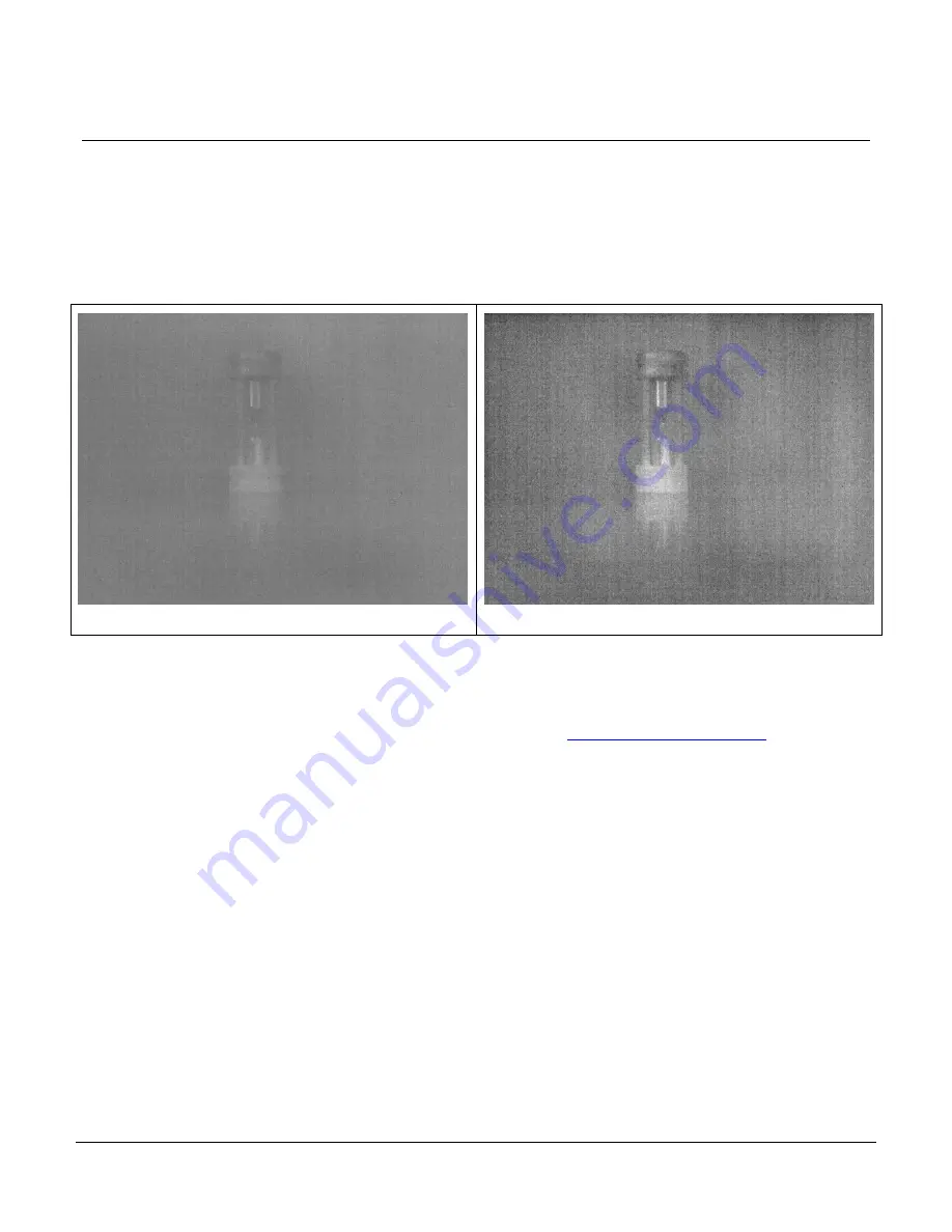
The Calibir camera supports two sensor gain settings: normal gain (1x) and high gain (3x). 
The high gain setting amplifies the analog signal output from the sensor, effectively increasing the 

temperature difference between pixel values. This can enhance scenes with small ranges of 

temperature differences but can also increase noise. 


Sensor Gain = 1x 


Sensor Gain = 3x 

Figure 5: Sensor Gain 

Related GigE Vision Features 

The sensorGain feature controls this setting and is part of the Sensor Control Category.  
 

Summary of Contents for CALIBIR 640 GigE

Page 1: ...CALIBIR 640 GigE IR Camera User s Manual sensors cameras frame grabbers processors software vision solutions July 10 2017 P N IRACUVM USER0 www teledynedalsa com...

Page 2: ...marks or intellectual property mentioned herein belong to their respective owners About Teledyne DALSA Teledyne DALSA is an international high performance semiconductor and electronics company that de...

Page 3: ...Fiber Optic Interface Requirements 17 QUICK START GUIDE 18 CONNECTING THE CALIBIR 640 GIGE VISION CAMERA 18 Power Specifications 18 Steps For Camera Startup 18 Calibir 640 GigE Connectors 19 Preventin...

Page 4: ...GigE Server Status 53 Optimizing the Network Adapter used with Calibir GigE 54 Quick Test with CamExpert Windows 54 About the Device User ID 55 USING CAMEXPERT WITH CALIBIR GIGE CAMERAS 56 CAMERA INF...

Page 5: ...the Sensor 94 Protecting Against Dust Oil and Scratches 94 Cleaning the Sensor Window 94 TROUBLESHOOTING 95 OVERVIEW 95 QUICK RECOVERY GUIDE 95 GENERAL TROUBLESHOOTING FOR CALIBIR 640 SERIES 97 Error...

Page 6: ...erlay 50 Figure 25 GigE Server Tray Icon 53 Figure 26 GigE Pop up Menu 53 Figure 27 GigE Vision Device Status 54 Figure 28 Sapera CamExpert 55 Figure 29 Sapera CamExpert GUI Layout 57 Figure 30 CamExp...

Page 7: ...igures 7 Figure 49 Ruggedized RJ45 Ethernet cable with Thumbscrews 93 Figure 50 Random Bad Data or Noise Example 100 Figure 51 Theoretical Ranges for a 1 7 x 0 5m Human Target 103 Figure 52 Theoretica...

Page 8: ...amples 43 Table 9 GigE Server Tray Icon States 53 Table 10 CamExpert Display Pane Control Buttons 56 Table 11 Camera Information Feature Descriptions 59 Table 12 Sensor Control Feature Descriptions 64...

Page 9: ...DALSA s Sapera LT SDK Within the Sapera LT SDK we currently offer a generic GigE Vision driver that supports all Teledyne DALSA GigE Vision cameras including all future Calibir GigE Vision cameras Th...

Page 10: ...B M25 lens Mount 29mm x 29mm x 61 13mm with lens mount M34 lens Mount 37 0mm x 37 0mm x 59 26mm with lens mount Mass without lens Calibir 640 Core M25 lens Mount 38g M34 lens Mount 39g Calibir 640 Gig...

Page 11: ...ifference Typ 116mK f 1 298K 30Hz Default Tint Gain Typical Response 20DN K unstretched 14 bit image Effective Dynamic Range approx 100 o C centered around 30o C 25 o C ambient Focal Plane Array 640x4...

Page 12: ...For currently supported lenses contact your Teledyne DALSA sales representative For Teledyne DALSA sales office details see the Contact Information section Teledyne DALSA Development Software Table 2...

Page 13: ...lectrostatic fast transient immunity IEC 61000 4 4 2012 2 kV power 1 kV I O Surge immunity IEC 61000 4 5 2005 1 kV L L 2 kV L Ground Magnetic field immunity IEC 61000 4 8 2009 30 A m 50 Hz Voltage dip...

Page 14: ...cation which defines device capabilities This description takes the form of an XML device description file respecting the syntax defined by the GenApi module of the GenICam specification For more info...

Page 15: ...gE The following information is a guide to computer and networking equipment required to support the Calibir GigE camera at maximum performance The Calibir camera series complies with the current IPv4...

Page 16: ...modified to write required values to parameters called features in GenICam For example in C it can be implemented as m_AcqDevice SetFeatureValue PixelFormat Mono14 Ethernet Switch Requirements for Ca...

Page 17: ...Point GX from Omnitron Systems www omnitron systems com converts GigE to fiber transmission and vice versa It supports multimode MM fiber over distances of up to 220 m 720 ft and single mode SM fiber...

Page 18: ...ng requirements Table 4 Calibir 640 GigE Power Specifications Feature Specification DC Voltage 12V 24V minimum 9V maximum 57V Watts 3 7W peak consumption Steps For Camera Startup Apply power to the ca...

Page 19: ...be solved by proper ESD management The Calibir camera when used with a simple power supply and Ethernet cable is not properly connected to earth ground and therefore is susceptible to ESD caused probl...

Page 20: ...P address can be assigned refer to the Network Imaging manual Preferably a DHCP server is present on the network where the Calibir issues a DHCP request for an IP address The DHCP server then provides...

Page 21: ...640 GigE camera using the Device Selector Click the Grab button for live acquisition Adjust the lens as required if no lens is available select a test pattern from the Image Format Feature Category If...

Page 22: ...he bit range of the display window to view specific pixel ranges that contain relevant image data To do so right click on the display window and select Display Setting In the Display Setting dialog us...

Page 23: ...ons describe features and configuration options These include Heat Sinks Adjusting the Lens Focus LED IndicatorsSensor Gain Fixed Pattern Noise Correction Overlays Metadata Horizontal Image Flip Media...

Page 24: ...edyne DALSA recommends that the Calibir camera be mounted using heat sinks to optimize shutterless operation Refer to the Mechanical Specifications section for information on the exact size and positi...

Page 25: ...era Initial state on power up before flashing Remains as steady Red only if there is a fatal error Camera is not initialized Initialization sequence in progress IP address assigned Application connect...

Page 26: ...tting amplifies the analog signal output from the sensor effectively increasing the temperature difference between pixel values This can enhance scenes with small ranges of temperature differences but...

Page 27: ...tion coefficients can be saved to non volatile camera memory When enabled the FPN correction is applied in addition to shutterless FPN correction FPN Compensation Mode Off FPN Compensation Mode Active...

Page 28: ...example a halo or vignetting effect This may be caused by the environmental conditions or the particular camera installation for example how the camera is mounted the type of heat sinks or airflows p...

Page 29: ...perature at which it was calculated the further the camera operating temperature is from the correction point the less accurate the correction To compensate for this effect FPN compensation mode can b...

Page 30: ...r selects the lens from the list of available lenses To be accurate the lens temperature has to be stable and the one point FPN calibration has to be done at that lens temperature otherwise this featu...

Page 31: ...OI overlays can be used to highlight specific regions Their colors are configurable The false color legend indicates the relative intensity of the different colors The frame counter increments with ea...

Page 32: ...pixels UINT64 frameTimestamp Value of the camera s internal clock increments every microsecond at the moment where the sensor started outputting an image UINT16 roiX X coordinate of the top left corne...

Page 33: ...cameras can select the polarity of pixels as required This allows white pixels 255 to represent either hotter or colder elements in the scene Pixel Polarity White Hot Pixel Polarity White Cold Figure...

Page 34: ...l image flip operation Image Flip Horizontal False Image Flip Horizontal True Figure 12 Horizontal Image Flip Note FPN correction needs to be recalibrated after the horizontal flip has been activated...

Page 35: ...s applied to the entire image and can be used to reduce image noise and other artifacts The following examples use a zoomed image to show the effects of the median filter at pixel level Median Filter...

Page 36: ...gurable parameters include the size of the neighborhood window and the threshold uses to identify bad pixels the number of standard deviations from the average value To generate valid results a unifor...

Page 37: ...ra User s Manual Features and Configuration Options 37 The File Access Control dialog in CamExpert provides file access to the User Defect Pixel Map through the Miscellaneous file type category Figure...

Page 38: ...s provide less contrast less stretching of values while higher values stretch a smaller range in the original 14 bit image Recommended values for most applications is between 100 and 150 When contrast...

Page 39: ...nds on the average pixel value of the scene The adaptive contrast enhancement algorithm allows for scene dependent optimized contrast while still being able to fine tune the range compression rather t...

Page 40: ...40 Features and Configuration Options Calibir 640 GigE IR Camera User s Manual Bit Range 2 9 Bit Range 3 10 Bit Range 4 11 Bit Range 5 12 Bit Range 6 13...

Page 41: ...th increasing saturation Note that the recommended settings between 60 and 100 provide the greatest dynamic range while minimizing saturation as seen in the histograms below for contrast settings of 5...

Page 42: ...libir 640 GigE IR Camera User s Manual Contrast 150 Limit 1 Average value 128 10 Standard Deviation 65 03 Contrast 200 Limit 1 Average value 130 79 Standard Deviation 92 74 Contrast 255 Limit 1 Averag...

Page 43: ...ler effect as the scene has less range than the limit itself The following examples show that for a low contrast scene where the majority of information resides in a range of 25 DN using default param...

Page 44: ...44 Features and Configuration Options Calibir 640 GigE IR Camera User s Manual Contrast 255 Limit 50 Contrast 255 Limit 100 Contrast 255 Limit 150...

Page 45: ...Options 45 Contrast 255 Limit 200 Contrast 255 Limit 255 Related GigE Vision Features The rangeCompressionContrast rangeCompressionContrastLimitMode and rangeCompressionContrastLimit features control...

Page 46: ...mage is filled vertically with an image that goes from the darkest possible value to the brightest Figure 18 Vertical Ramp Test Pattern Diagonal ramp combination of the 2 previous schemes Figure 19 Di...

Page 47: ...ate image boundaries diagonal lines to validate field order and center circle to validate aspect ratio Figure 21 Alignment Pattern Related GigE Vision Features For the Calibir 640 GigE the TestImageSe...

Page 48: ...rrent operating temperature in Celsius Available sensors are Processor FPGA chip Sensor microbolometer sensor Controller MSP mixed signal processor chip note this component may be eliminated in future...

Page 49: ...ll 4 error log memory locations are used no new error logs are written to non volatile memory to enable writing of new error logs the error logs must be cleared Related GigE Vision Features The crashL...

Page 50: ...lor map can be uploaded using the File Access Control dialog select the Miscellaneous file type and False Color Map as the file The file bmp must be a one line 256 column 24 bit per pixel bitmap The X...

Page 51: ...f Calibir GigE will be used in a third party GigE Vision Compliant environment Sapera or Sapera runtime is not required and you need to follow the installation instructions of the third party package...

Page 52: ...to control the camera Procedure Download and install Sapera 8 10 which automatically provides GigE Vision support Connect the camera to an available Gigabit NIC Refer to Sapera LT User s Manual concer...

Page 53: ...server tray icon when the a device is not found This indicates a major network issue Or in the simplest case the device is not connected If you place your mouse cursor on this icon the GigE Server wil...

Page 54: ...by double clicking the desktop icon created during the software installation CamExpert will search for installed Sapera devices In the Device list area on the left side the connected Calibir GigE cam...

Page 55: ...x devices as an example Non Teledyne DALSA cameras are labeled as GigEVision Device Click on a device user name to select it for control by CamExpert An imaging application uses any one of these attri...

Page 56: ...ng or changing all acquisition parameters supported by the acquisition device CamExpert displays parameters only if those parameters are supported by the installed device This avoids confusion by elim...

Page 57: ...Calibir 640 GigE IR Camera User s Manual Operational Reference 57 Figure 29 Sapera CamExpert GUI Layout...

Page 58: ...es based on their visibility attribute and provides quick Visibility level selection via controls below each Category Parameter list Less More The user can also choose the Visibility level from the Vi...

Page 59: ...es listed in the description table but tagged as Invisible are usually for Teledyne DALSA or third party software usage not typically needed by end user applications Figure 30 CamExpert Camera Informa...

Page 60: ...None No lens type associated with the camera Standard Standard Standard lens type For currently supported lenses contact your Teledyne DALSA sales representative For Teledyne DALSA sales office detai...

Page 61: ...ts power up state W Beginner Power up Configuration Selector UserSetDefaultSelector Selects the camera configuration set to load and make active on camera power up or reset The camera configuration se...

Page 62: ...elated to the resource manager SaveGenericError Unknown error SaveBusyError The camera is busy and cannot perform the action SaveMemoryError Camera ran out of memory while saving set SaveFileError Int...

Page 63: ...or The user chooses from one factory data set or a user saved set Load Save Configuration The second drop list allows the user to change the camera configuration any time after a power up see feature...

Page 64: ...evice uses an Areascan sensor Sensor Width SensorWidth Defines the sensor width in active pixels RO Beginner Sensor Height SensorHeight Defines the sensor height in active lines RO Beginner Sensor Col...

Page 65: ...e various Trigger features Beginner Frame Acquisition Trigger AcquisitionStart Enables the selection of a trigger source that starts the Acquisition of one or many frames Trigger Mode TriggerMode Cont...

Page 66: ...oupled Line Mode LineMode Reports if the physical Line is an Input or Output signal RO See Input Signal Electrical Specifications Expert Input Input The line is an input line Output Output The line is...

Page 67: ...anual Operational Reference 67 External Trigger SOF Frame acquisition External Trigger debounced tdebounce tdebounce tdebounce tdebounce tdebounce Frame Timestamp ttrig to acq rising edge active Figur...

Page 68: ...formation as provided by PixelCoding PixelSize PixelColorFilter combined in one single value Beginner Monochrome 8 Bit Mono8 Monochrome 8 Bit This format automatically employs the Range Compression me...

Page 69: ...age is filled horizontally with an image that goes from the darkest possible value to the brightest by 1 Dn increment per pixel and per line Constant incrementing Purity Image pixels all have the same...

Page 70: ...iew attribute Additionally the view column will indicate which feature is a member of the DALSA Features Naming Convention denoted by DFNC versus the GenICam Standard Features Naming Convention SFNC t...

Page 71: ...e Descriptions Display Name Feature Values Description View Pixel Polarity pixelPolarity Output image pixel polarity Beginner DFNC White Cold WhiteCold White pixels indicate colder temperatures White...

Page 72: ...ent Defective pixels are replaced with the average value of the neighboring valid pixels Defective Pixel X Coordinate defectivePixelXCoordinate Specifies the X coordinate of the pixel in the defective...

Page 73: ...ginner DFNC Off Off Disable overlay display Active Active Enable display of overlays Overlay Selector overlaySelector Selects the graphic overlay for which to modify settings Beginner DFNC Black backg...

Page 74: ...DFNC Overlay color red overlayColorR Sets the overlay red RGB color value 0 255 Currently the reticle and ROI overlays support user defined color Beginner DFNC Overlay color green overlayColorG Sets t...

Page 75: ...to insert between each packet for this stream channel Expert Interface MAC Address GevMACAddress MAC address of the network interface Beginner Packet Resend Buffer Size devicePacketResendBufferSize In...

Page 76: ...ted interface Invisible LLA LLA Link Local Address Mode DHCP DHCP Dynamic Host Configuration Protocol Mode Network requires a DHCP server PersistentIP PersistentIP Persistent IP Mode static Persistent...

Page 77: ...ers are highly dependent on the number of cameras connected to a NIC the data rate of each camera and the trigger modes used Information on these features is found in the Teledyne DALSA Network Imagin...

Page 78: ...le Operation Execute feature is called Guru Open Open Select the Open operation executed by FileOperationExecute Close Close Select the Close operation executed by FileOperationExecute Read Read Selec...

Page 79: ...gory From the File Type drop menu select the file Type that will be uploaded to the Calibir GigE This CamExpert tool allows quick firmware changes or updates when available for your Calibir GigE model...

Page 80: ...Technical Specifications Calibir 640 GigE IR Camera User s Manual Technical Specifications Mechanical Specifications Calibir 640 GigE with M25 Lens Mount Figure 42 Calibir 640 GigE with M25 Lens Moun...

Page 81: ...Calibir 640 GigE IR Camera User s Manual Technical Specifications 81 Calibir 640 GigE with M34 Lens Mount Figure 43 Calibir 640 GigE with M34 Lens Mount...

Page 82: ...A provides an open ended breakout cable If other mating cables are required ensure that cables are compatible with this connector Samtec Part Number TFM 110 02 L D LC Teledyne DALSA makes available op...

Page 83: ...on 12 Volt Supply 2 7W typical 2 83W typical Input Power Consumption 24 Volt Supply 2 7W typical 2 8W typical Input Power Consumption 48 Volt Supply 2 98W typical 3 07W typical Absolute Maximum DC Pow...

Page 84: ...see table below If using a differential signal driver only one input can be used due to the shared input common see details below External Input DC Characteristics Operating Specification Minimum Maxi...

Page 85: ...8mA User IO Ground User IO Power 3V 35V 10 9 8 7 6 5 4 3 2 1 Camera IO Interface B E Common Ground Imax 8mA External Signal 0 Input 0 C External Input Using Common Emitter NPN Driver External Input m...

Page 86: ...cal Specifications Calibir 640 GigE IR Camera User s Manual External Input Using a Balanced Driver RS 422 Compatible Transmitter 10 9 8 7 6 5 4 3 2 1 Camera IO Interface Common Ground Input 1 External...

Page 87: ...uter NIC supporting PoE or a PoE capable Ethernet switch or an Ethernet power injector Important Connect power via the I O connector or PoE but not both Although Calibir 640 GigE has protection differ...

Page 88: ...88 Technical Specifications Calibir 640 GigE IR Camera User s Manual EC FCC Declarations of Conformity...

Page 89: ...Calibir 640 GigE IR Camera User s Manual Technical Specifications 89...

Page 90: ...2 Option Discrete Cable Assembly www samtec com technical specifications Default aspx SeriesMaster SFSD Samtec ISDF 05 D ISDF 05 D M Discrete Connector www samtec com technical specifications Default...

Page 91: ...Technical Specifications 91 Cable Assembly G3 AIOC BLUNT2M Open ended cable assembly to connect to Samtec 10 pin connector with thumbscrews Figure 45 Cable Assembly G3 AIOC BLUNT2M Figure 46 Cable Ass...

Page 92: ...amera User s Manual Cable Assembly G3 AIOC BRKOUT2M Cable with terminal block breakout to connect to the Samtec 10 pin connector with thumbscrews Figure 47 Cable Assembly G3 AIOC BRKOUT2M Figure 48 Ca...

Page 93: ...e cables are recommended when Calibir is installed in a high vibration environment All Calibir 640 series camera versions support this secure Ethernet cable Review their catalog for all available vers...

Page 94: ...surface of the window barehanded will leave oily residues Using rubber finger cots and rubber gloves can prevent oil contamination However the friction between the rubber and the window may produce e...

Page 95: ...and network adapters which have caused problems with Calibir Emphasis is on the user to perform diagnostics with the tools provided and methods are described to correct the problem Quick Recovery Gui...

Page 96: ...ver Automatic IP DHCP Sapera Network Imaging Driver Enabled Included in the Discovery Process The camera should then be visible to the host computer s software When placing the mouse cursor over the G...

Page 97: ...is off the power supply is not connected or faulty Verify the power supply voltage Camera is functional but image has no contents Aim the Calibir at an object with a temperature considerably higher l...

Page 98: ...s indicates either a major camera fault or condition such as disconnected power or a network issue where there is no communication Refer to the Quick Start Guide and Camera Connection Setup sections t...

Page 99: ...network issues may still not perform optimally Operational issues concerning cabling Ethernet switches multiple cameras and camera exposure are discussed in the following sections Always Important Po...

Page 100: ...l configuration parameters seem correct and the Ethernet cable is secure The following image shows an example of this type of bad acquisition while testing a Calibir installation with CamExpert Figure...

Page 101: ...started Cabling and Communication Problems Use a shielded cable where the connector shell electrically connects the Calibir chassis to the power supply earth ground Check that the Ethernet cable is cl...

Page 102: ...were any problems with the automatic Calibir software installation Before Contacting Technical Support Carefully review the issues described in this Troubleshooting section To aid Teledyne DALSA perso...

Page 103: ...ion An object is present Orientation Object is symmetrical asymmetric horizontal or vertical Recognition The type of object can be discerned for example a person vs a vehicle Identification A specific...

Page 104: ...104 Appendix Range Performance Calibir 640 GigE IR Camera User s Manual Theoretical Ranges for a 2 3 x 2 3m NATO Target Figure 52 Theoretical Ranges for a 2 3 x 2 3m NATO Target...

Page 105: ...eb site www teledynedalsa com corp contact Email mailto info teledynedalsa com Technical Support Submit any support question or request via our web site Technical support form via our web page Support...

Reviews: