DALBO POWERROLL 1430 Manual Download Page 28


POWERROLL 


Side 28 


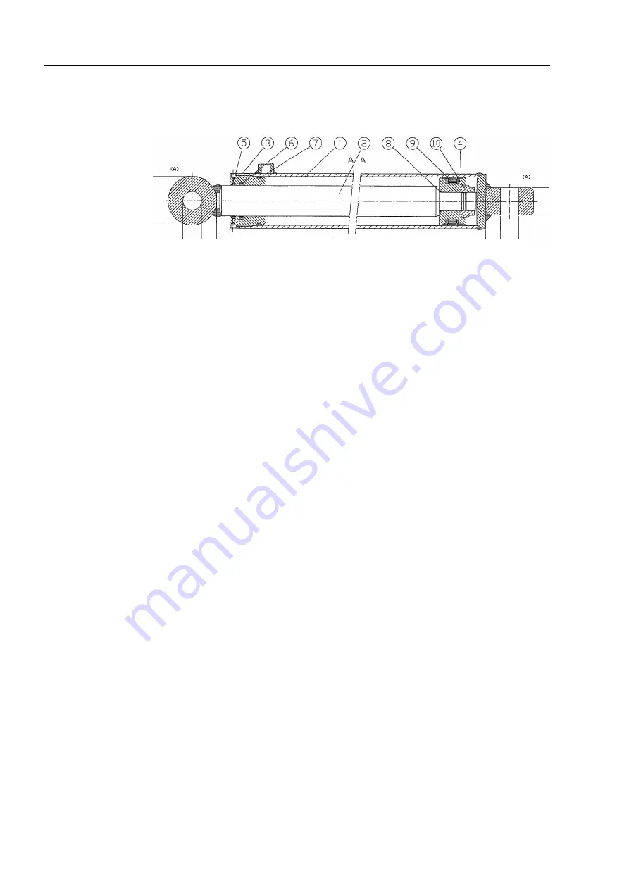
Replacing gaskets on raise/lower cylinder 

Fig. 21 


1.


Drain oil from cylinder by moving ram carefully backwards and forwards. 

2.


Extend ram to centre position. Unscrew upper part (pos. 3) from cylinder tube 
(pos. 1). Use special tool to remove upper part. If upper part is stuck, heat front 
of upper part. When upper part is detached from cylinder tube, pull ram up to-
wards upper part and remove completely from cylinder tube (pos. 1). 

3.


Remove lock nut (pos. 10) retaining collar shoe (pos. 4). 

4.


Remove collar shoe (pos. 4) from ram, (pos. 2). 

5.


Remove upper part (pos. 3) from ram, (pos. 2). 

6.


Remove gaskets in upper part (pos. 5+6+7+8+9) along with collar shoe. 

7.


Clean  all  parts  and  check  for  particles  etc.  Check  for  rust  around  scraper  ring 
(pos. 5) in upper part. If detected, remove thoroughly. 


Assembly 

1.


Fit new gaskets (pos. 5+6+7+8+9) in upper part, plus collar shoe. 

2.


Lubricate thread in upper part (pos. 3) and cylinder tube (pos. 1) with oil. 

3.


Remove upper part (pos. 3) on ram shaft. 

4.


 Remove collar shoe (pos. 4) and screw on lock nut, 

secure with Loctite

. Ensure 

that thread is absolutely clean and free of oil or other impurities before applying 
Loctite.

 Do not fill with oil for 12 hours after use of Loctite.


5.


Lubricate  outer  collar  shoe  gasket  in  contact  with  cylinder  tube  and  inside  of 
cylinder tube with oil, push ram into centre position. 

6.


Fit upper part onto cylinder tube and tighten. 

7.


For fitting cyl

inder see ”

Replacing raise/lower cylinder

”.


Summary of Contents for POWERROLL 1430

Page 1: ...POWERROLL ENG 1430 1530 1630 1830 Serial no 100 XXX ...

Page 2: ......

Page 3: ... number A spare parts list is included at the back of this manual EU DECLARATION OF COMPLIANCE DALBO A S DK 7183 Randbøl 4575883500 declares herewith that the above machine is manufactured in accordance with the provisions of directive 2006 42 EC which replaced directive 98 37 EC and change directives 91 368 ECC 93 44 ECC and 93 68 ECC on harmonisation of member state legislation con cerning healt...

Page 4: ...EIGHT 14 ADJUSTING MID SECTION 15 OPERATION 16 EXTENDING AND RETRACTING 16 Extending 16 Retract 17 ADJUSTMENT OF HYDRAULIC WEIGHT TRANSFER 19 Excessive pressure 19 Insufficient pressure 19 OPERATING SPEED 20 Power 20 TROUBLESHOOTING 21 MAINTENANCE 22 LUBRICATION 22 ADJUSTMENT 23 Adjustment of rollers 23 Wheels 23 HYDRAULICS 24 REPLACEMENT AND REPAIRS 25 HYDRAULICS 25 Replacing fold extend cylinder...

Page 5: ...28 Assembly 28 REMOVAL FITTING WHEEL 29 Replacing wheel bearings 29 REMOVING ROLLER AXLES 29 Replacing side section axles 30 Fitting axles with roller rings 30 Replacing the centre axle 31 REPLACING AXLES BEARINGS OR ROLLER RINGS 31 Crosskill ring 32 SCRAPPING 33 SPARE PARTS 34 ...

Page 6: ... machine s working radius before oper ating Operate machine only from inside the tractor When the machine is folded together check the side sections are locked Check all control handles are secured against accidental operation Before leaving the tractor or making adjustments performing maintenance or repairs on the roller extend fully and lower to ground or maintain in transport position apply tra...

Page 7: ...vere injury In the event of injury seek medical help immediately Assembly Danger of crushing Ensure no personnel are between implement and tractor or between the parts to be connected Maintenance and repair Ensure machine is adequately supported or fully extended for all repair and maintenance work Ensure tractor and machine are properly braked engine stopped and ignition key removed Tighten all s...

Page 8: ...ir instructions and that original spare parts are always used The roller may only be used maintained or repaired by personnel familiar with it and who are aware of the risks that can be involved The manufacturer cannot be held liable for injury or damage arising from modifi cations made to the machine performed without prior permission from the manufacturer Neither can the manufacturer be held lia...

Page 9: ...0 1630 1830 HP recommended Min 200 Min 215 Min 230 Min 250 Gross weight kg Cambridge Breaker 50 8 440 8 675 8 880 9 820 Cambridge Breaker Plus 50 8 610 8 855 9 075 10 040 Cambridge Breaker 55 9 750 10 065 10 380 11 500 Cambridge Breaker Plus 55 10 135 10 480 10 820 12 000 Crosskill 53 7 620 7 700 7 950 8 770 Crosskill 60 9 410 9 700 9 990 11 060 Sections pcs 5 5 5 5 Hydraulic requirements 4 DV X X...

Page 10: ... manual is divided into 5 main sections Safety Starting routine and running Accessories Maintenance Repairs The following symbols represent Points which are important to functionality and service life Points relevant to safety Delivery The machine is delivered complete on a trailer If lifting the roller we recommend the use of straps on the mid section and drawbar to maintain balance ...

Page 11: ...ch the sections are independent of each other Hydraulic weight transfer is standard on all models POWERROLL 1630 POWERROLL is used after sowing to improve sprouting and compress stones POWERROLL can also be used for breaking up a compressed soil surface in wheat fields or grassed areas POWERROLL can be fitted with compressed air brakes instead of the standard hy draulic brakes ...

Page 12: ...OLL onto its wheels and down into working position Fold Weight transfer of innermost side frames Red Double acting Folds the inner side sections together out and acts as weight transfer from the mid section to the inner side sections Fold Weight transfer of outermost side frames Black Double acting Folds the outer side sections together out and acts as weight transfer from the mid section to the o...

Page 13: ...port leg ball cock to activate support leg outlet Close ball cock remove tow bar pin and disconnect hydraulic hoses Remember to depressurise hoses before disconnecting them POWERROLL must be in transport or working position when disconnecting ...

Page 14: ...t be correctly positioned Fig 3 Before adjusting drawbar to tractor basic setting must be correct Put the roller on the support leg and check distance between flange underside and ground is 40 cm Adjust drawbar to tractor from this basic position Incorrect drawbar height can cause uneven operation as the roller will not apply equal pressure for all sections Fig 4 To achieve optimum drawbar height ...

Page 15: ... mid section Fig 5 Fully extend roller on a level surface see Operation check pipe A on mid section is horizontal in direction of travel This must be done after the drawbar is adjusted and with POWERROLL attached to the tractor A ...

Page 16: ...ormed with tractor parked Extending Fig 6 1 Lift side sections from transport hook A using raise lower cylinder marked white Fig 6 Fig 7 2 Activate cylinders marked red for extend fold of innermost side frames and fully extend side sec tions Fig 7 3 Activate cylinders marked black for extend fold of outermost side frames and fully extend side sec tions Fig 8 4 Activate raise lower cylinder to low ...

Page 17: ... side sections A and the outermost of the innermost side sections B are slightly raised Both manometers must read 0 bar Fig 11 2 Activate raise lower cylinders marked white to full length Roller will lift from ground Fig 12 3 Activate fold extend cylinders for the outermost side frames marked black again to fold these side sections fully in 4 Activate fold extend cylinders for the innermost side f...

Page 18: ...k again to fold these side sections fully in 5 Lower the side frames into the transport hooks using the raise lower cylinders marked white When the transport hooks engage set the hoses marked white into flow position Fig 14 ...

Page 19: ...be necessary to adjust pressure according to soil conditions Excessive pressure 1 The pressure on the outer rings of the innermost side sections will be too high The rings will be pressed too heavily into the soil leaving a clear groove after the side sections The pressure on the outer side sections will also be too high 2 The mid sections will not apply sufficient pressure leaving the soil higher...

Page 20: ...is recommended but always operate according to conditions Increased speed will increase wear particularly in dry conditions The rings can also be damaged if operating at excessive speeds in unfavorable conditions Power Power requirement will depend on soil type terrain and speed Table 2 Guide to power requirement in HP Model cm 1430 1530 1630 1830 HP Min 200 Min 215 Min 230 Min 250 ...

Page 21: ...djust drawbar and mid section see Adjusting drawbar height and Adjusting mid section Mid section not horizontal Adjust drawbar and mid section see Adjusting drawbar height and Adjusting mid section Pressure on mano meter dropping Handle not in flow setting Adjust pressure on weight transfer and set handle to flow setting see Adjustment of hydraulic weight transfer Driver operated non return valve ...

Page 22: ...ins and bolts to avoid mechanical failure Check hydraulic system for leaks Lubrication Fig 16 A B C D E Lubrication points Number of nipples Lubrication inter vals hours Illustration Cylinder for extending side sections 8 50 A Rotation pin for extending side sec tions 4 50 B Outer outrigger arm 2 50 C Inner outrigger arm 4 50 D Drawbar main frame 2 50 E Lubricate all lubrication points at least on...

Page 23: ...e shaft sev eral times to ensure they bite firmly into the shaft Wheels Lubricate and adjust wheel bearings at least once annually Check tyre pressures see recommended pressure on tyre Adjustment and lubrication of wheel bearings 1 Remove hub caps 2 Remove split pin 3 Tighten castle nut 1 6th of a turn until hole aligns with axle Turn wheel check for resistance A little play should be detected in ...

Page 24: ...aulics Check all hydraulic hoses for wear or cracks Check all hoses for crimping Lubricate exposed rams with oil or pressure resistant grease to avoid rust forming when storing for long periods Remember to remove before use ...

Page 25: ...ork depressurise hydraulic system and support part being worked on Always ensure hydraulic system is bled after repairs and before use to prevent me chanical breakdown and injury to person Hydraulics Replacing fold extend cylinder for side sections inner Perform repairs with POWERROLL fully extended and resting on the ground in work ing or transport position Fig 18 1 Depressurise cylinders Check t...

Page 26: ...e sections 2 Drain oil from cylinder by moving ram carefully backwards and forwards 3 Extend ram to centre position Unscrew upper part pos 3 from cylinder tube pos 1 Use special tool to remove upper part If upper part is stuck heat front of sleeve When upper part is detached from cylinder tube pull ram up towards upper part and remove completely from cylinder tube 4 Remove lock nut retaining colla...

Page 27: ...ide of cylinder tube with oil push ram into centre position 6 Fit upper part onto cylinder tube and tighten 7 Fit cylinder see Replacing fold extend cylinder for side sections Replacing raise lower cylinder Fig 20 Fold POWERROLL out or leave in transport position Depressurise raise lower cylinder A 1 Disconnect hoses from cylinder 2 Support cylinder 3 Remove split pins in pins remove pins 4 Remove...

Page 28: ... 6 7 8 9 along with collar shoe 7 Clean all parts and check for particles etc Check for rust around scraper ring pos 5 in upper part If detected remove thoroughly Assembly 1 Fit new gaskets pos 5 6 7 8 9 in upper part plus collar shoe 2 Lubricate thread in upper part pos 3 and cylinder tube pos 1 with oil 3 Remove upper part pos 3 on ram shaft 4 Remove collar shoe pos 4 and screw on lock nut secur...

Page 29: ...astle nut pos 19 4 Hub housing can now be removed from shaft 5 Remove bearings pos 17 18 6 Fit seal ring pos 19 Assembly 1 Fit bearing outer rings pos 17 18 in hub housing pos 22 2 Remove seal ring pos 16 3 Fit bearing inner ring pos 18 on axle pos 2 and fit axle in hub housing 4 Fit bearing inner ring pos 17 on axle pos 2 5 Screw castle nut onto axle pos 2 whilst turning hub housing pos 22 Tight ...

Page 30: ... section arm on side section Tighten straps until bolts A are loose and can be removed 3 Activate raise lower cylinder lift roller onto wheels 4 Roll axle with roller rings from roll er If there is no crane available activate roller weight transfer a little until bolts are loose and can be removed Fitting axles with roller rings 1 Position axles with roller rings and bearings corresponding to that...

Page 31: ...round again and axle is free 5 Roll axle with roller rings from roller 6 Reverse procedure for assembly Do not activate hydraulics if there are personnel within machine extension radius Replacing axles bearings or roller rings Fig 25 1 Slacken bearing screws A and withdraw bearings 2 Slacken stop ring bolts B and withdraw stop rings 3 Withdraw roller rings from axle 4 Reverse order to reassemble 5...

Page 32: ... slacken stop ring bolts a few times to ensure they bite into the axle When fitting axles with bearings remember to ensure the bearing lubrication nip ples face backwards upwards This gives easy access for lubrication and protects the nipples from stones Check that the roller rings are close together and the direction of rotation for the Crosskill rings Always finish with the small rings smallest ...

Page 33: ...f the weight of any given part when removing or disassembling All parts must be supported or lifted to avoid danger of falling Disconnect hydraulic hoses and cylinders and drain oil Collect oil in container to avoid pollution Send oil and hoses for destruction All iron used in the machine can be recycled ...

Page 34: ...POWERROLL Side 34 Spare parts ...

Reviews: